While they might appear mysterious at times, electronic throttle body (ETB) and accelerator position pedal (APP) system technologies aren’t complicated if we apply a foundational concept to the many different vehicles passing through our service bays. Using a 2016 Nissan Frontier equipped with the 4.0-liter, 24-valve engine to represent a specific hardware configuration, I’ll discuss some very common ways to find those uncommon and perhaps intermittent throttle control faults.
Shared Signals
Nissan uses two accelerator pedal position (APP) sensors to transmit a throttle position command from the driver to software integrated into the engine control module (ECM). Some applications might also use a separate module to control the ETB (for our purposes, we’ll use the term “module” to indicate either configuration).
The APP sensor signals are sent to the module, which controls the throttle position by using a 12-volt, pulse-modulated power supply to pull against a clock spring-loaded throttle plate. The real-time throttle position is reported to the module through two throttle position sensors. As pulse modulation duty cycle increases, the ETB’s throttle plate opens until it meets the command requirements of the APP.
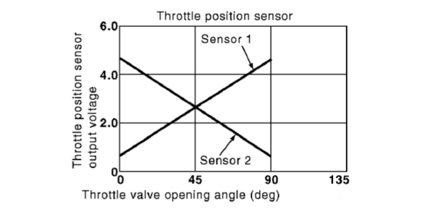
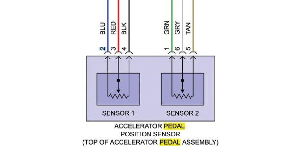
Our Frontier generates two APP voltage outputs, one ascending voltage and one descending voltage (see Photo 1). The ECM evaluates the accuracy of these signals when both intersect. Similarly, the ETB contains two throttle position sensors, one ascending voltage and one descending voltage, to verify the commanded position of the throttle plate. If the ETB or APP signals fail to intersect at the correct point, a diagnostic trouble code is stored and the “check engine” (CE) light will illuminate or an optional electronic throttle malfunction warning light might illuminate on the instrument panel.
Failsafe Mode
If the APP or the ETB ascending and descending signals don’t align at their predetermined intersection points, the module will enter a “fail-safe” or limp mode, which sets the throttle plate opening at a fixed value of about five degrees on Nissans. The limp mode can also be triggered by an electrical “glitch” in the ETB or APP circuitry. Depending upon the application, vehicle speed is generally limited from 10-30 mph on flat ground.
ETB Maintenance
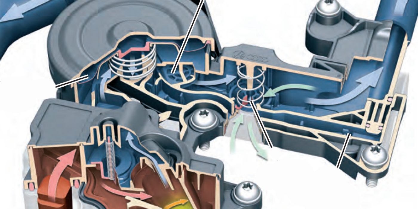
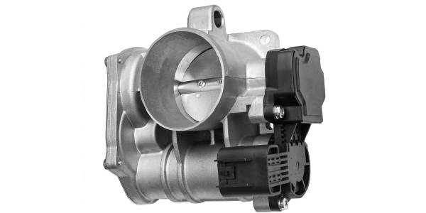
At closed throttle, a slight amount of clearance is maintained between the throttle plate and throttle bore to prevent the plate from contacting the bore. As a result, a small, predetermined volume of air flows between the throttle plate and bore, often called “base air,” which is built into the ETB’s idle speed calculations (see Photo 2).
The ETB/APP module must be able to consistently sense a specific closed-throttle voltage via its throttle position sensors. When the ETB can’t consistently duplicate closed throttle, it might operate in a default mode. And, when deposits reduce base air flow, idle speed calculations can become erratic, which can cause cold stalling and hot idle speed complaints.
Routine ETB cleaning consists of turning the ignition on with engine off, and blocking the throttle pedal wide-open for access. In severe cases, the ETB must be removed for cleaning. After applying a recommended throttle body cleaner onto the backside of the throttle plate and inner bore, carbon can be successfully removed using a toothbrush. Some penetrating oils are also specified for soaking away hard carbon build-ups on ETBs. Harsh solvents or aerosol carburetor cleaners are to be avoided since throttle shaft seals and deposit-resistant coatings on the throttle plate and bore surfaces can be ruined.
Service Information
Connecting a scan tool and retrieving diagnostic trouble codes (DTCs) are the first steps in diagnosing any throttle-related complaints. While generic P0-series and factory P1-series ETB codes are relatively few, one source lists 24 generic P2-series codes that are more complex and comprehensive. These codes are normally enough to pin-point sensor and circuit issues within the ETB or APP system. Although scan tool-based code definitions are handy, increase your diagnostic accuracy by accessing code enable criteria to define the set points and diagnostic procedures for these codes.
Wiring Diagrams
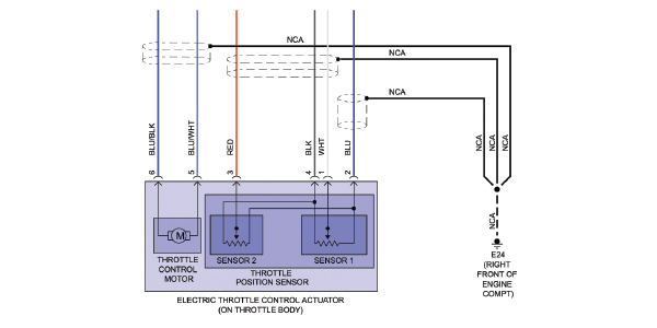
Looking at code-based ETB diagnostic processes, wiring diagrams are essential for determining the electrical relationships between the ETB, motor drive, throttle position sensors, APP systems and module (see Photos 3 and 4). Wiring diagrams, along with power flow and ground location charts, will fully illustrate power sources, reference voltages, bus communications and grounded circuits.
Intermittent Failures
Most ETB issues set codes, illuminate CE and ETB warning lights and place the module in limp mode. In some cases, normal throttle operation will return after the key is cycled on/off/on. This condition usually indicates an intermittent or random failure that can’t be immediately duplicated.
Connectivity Issues
Given enough stress or vibration, fretting corrosion can form inside a connector, which causes a voltage drop in one or more ETB connector pins. Many intermittent failures, especially those associated with sharp vehicle maneuvers, are often caused by connectivity problems within the ETB/APP connectors. Along with removing the root cause of the connector failure, the recommended repair is to replace both male and female connectors. In the real world, we’re often forced to wash the connector with electrical contact cleaner and coat the pins with dielectric or other high-temperature synthetic grease to help prevent future corrosion fretting.
Cold Weather Failures
Any ETB/APP system that is grounded to the engine ultimately grounds through the engine block to a battery’s negative connection. When cranking the engine in cold weather, amperage through the battery/engine block connection spikes as the starter is engaged. This amperage spike can overload a corroded engine-to-battery ground, which forces the ETB/APP module to go into limp mode immediately after starting the engine.
The ETB/APP module might “see” this reduction of amperage flow as an open-circuit condition. This condition might set an ETB/APP code or it might set some type of general voltage availability code. The fix for any suspected grounding issue is to disassemble the block ground, thoroughly clean both cable and block surfaces, coat the parts with anti-corrosion compound and reinstall with star washers and a new retaining bolt.
Connector Pinouts
On occasion, a new ETB or APP fails to solve an idle speed control problem. Before replacing either, use a wiring diagram or connector pin chart to perform a key-on, engine-off connector pin-out test to verify all circuits.
In one remarkable case of high idle speed, I found the 5-volt reference to the throttle sensors was missing at the ETB connector. Examining the wiring diagram, I quickly determined the ETB shares its 5-volt reference with the engine’s electronic oil pressure sensor. Tracing the 5-volt reference, I found the ETB’s reference voltage was shorted to ground inside the oil pressure sensor. A new oil pressure sensor fixed the high idle speed complaint.

Vacuum Leaks
In one rare case, I experienced a random 1,600-rpm fast idle condition on a domestic application. Since the engine idled at a perfect 1,600 rpm each time, I knew it was a default value. The code indicated a “gross vacuum leak” condition. Evidently, the gross vacuum leak didn’t occur until after extended brake operation. Even more puzzling, smoke and propane testing failed to locate any vacuum leaks.
According to an off-hand remark by the owner, his daughter and friends had tried to install a new sound system in Dad’s car. After removing three feet of black electrical tape, we discovered an amateur wiring repair at the APP assembly. We also found a ½˝ hole drilled through the firewall and into the rear chamber of the vacuum brake booster.
The ETB operating strategy for the gross vacuum leak evidently included fast-idling the engine to ensure good vacuum brake booster operation. A new brake booster solved the random fast idle complaint. Going back to a foundational understanding of electronic throttle operation, diagnosing those “uncommon failures” isn’t as difficult as you might think. iC
~
GARY GOMS is a former educator and shop owner who remains active in the aftermarket service industry. Gary is an ASE-certified Master Automobile Technician (CMAT) and has earned the L1 advanced engine performance certification. He also belongs to the Automotive Service Association (ASA) and the Society of Automotive Engineers (SAE).