 Although the best method to measure clearance between the crankshaft and crankshaft bearings is by using a bore gauge while the bearing is installed in the cylinder block or connecting rod, the question of measuring wall thickness of the bearings to calculate the clearances still comes up from time to time.
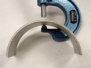
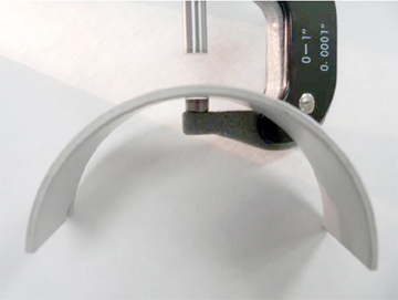
To measure the wall thickness of a main or rod bearing correctly the location on the bearing that you measure and the tool you use will determine the level of accuracy of the measurement. A micrometer with a ball anvil must be used to fit the curvature of the bearing I.D., as shown in Figure 1. Standard flat anvil micrometer, shown in Figure 2 will bridge across the curved I.D. and give false readings.
Micrometers with pointed or blade anvils and dial calipers should not be used as they can give false readings and damage the bearing surface. Obviously using an accurate, recently calibrated micrometer is a must for reliable measurement.
 Just as important as using the correct tool is the location on the bearing that is measured. Crankshaft bearings should be measured 90° to the parting line. By design most crankshaft bearings have an eccentric design, which means the wall thickness at the parting line is not equal to that at the 90° centerline.
The purpose of the eccentric design is to compensate for casting distortion during operation, create a “wedge” affect that promotes the formation of oil film, and for slight tolerance differences of the jointing components. To determine the amount of eccentricity, measure the bearing at the centerline and then at approximately 3/8” above the parting line since some bearings may also have an additional “relief” near the parting ends.
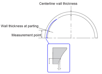 The amount of eccentric dimension and the presence of a relief cut vary by engine make and/or model. The centerline measurement determines the amount of clearance between the bearing and crankshaft and is the common dimension given when wall specifications are stated.
–Tech Tip courtesy of IPD (www.ipdparts.com).

