If you hadn’t noticed, the bright red “charge indicator” light on the dashboard has gone the way of carburetors and contact point ignitions on late-model imports. You might instead see a “battery warning” light indicating the battery’s state of charge (SOC) and state of health (SOH). In most cases, a low SOC indicates a problem with the charging system. In other cases, the battery warning light might also indicate that the battery’s SOH is poor.
ELD SYSTEMS
To better understand the concept of computer-controlled charging systems, let’s begin with the electric load detection (ELD) system used on a 2012 Honda DX with the 1.8-liter four-cylinder engine. In contrast to “old-school” charging systems, the ELD system might charge as high as 14.9 volts when the A/C clutch is engaged or as low as 12.4 volts when little or no electrical load exists. The ELD might also deactivate the alternator during the cranking mode.
As Honda’s ELD has evolved since its introduction in 1988, its electrical architecture forms the basis of the computer-controlled charging systems in use today. The Honda ELD, for example, measures amperage flow through a battery load sensor located on the battery negative terminal or in the underhood fuse box.
The alternator and internal voltage regulator are connected to battery positive through a 100-amp fuse located in the underhood fuse box. The ECM controls charging voltage via a square-wave signal sent through a Local Interconnect Network (LIN) communications wire to the voltage regulator. The voltage regulator adjusts charging voltage by pulse-modulating alternator field voltage to meet operating conditions.
When the ELD’s battery load sensor detects a battery discharge, the ECM increases charging voltage to recharge the battery and support the vehicle’s electrical load. If the battery continues to discharge, ECM transmits that data through a two-wire F-CAN transceiver producing F-CAN high and F-CAN low signals. During a discharge condition, the central processing unit (CPU) located in the Gauge Control Module activates a charging system warning light to alert the driver of an impending battery failure.
Once the ELD system appeared in 1988, import techs learned very quickly that Step 1 before testing a Honda alternator is to create an electrical load by turning on headlamps and exterior lighting or the heater blower motor. Step 2 is to understand that the charging voltage may vary between 12.4 and 14.5 volts, depending upon electrical load.
BATTERY CHEMISTRY
When researching this column, I discovered that defective batteries were responsible for about 75 percent of dead battery complaints on Honda ELD systems. It stands to reason that understanding basic battery chemistry is a vital first step toward understanding how an ECM might diagnose a failing battery.
When a lead-acid battery is fully charged, its negative plates exist as pure lead while its positive plates exist as lead dioxide. The electrolyte is a solution of pure water and pure sulfuric acid, which creates a specific gravity 1.250 times heavier than pure water when the battery is fully charged.
As the battery discharges, the positive and negative plates absorb sulfur from the electrolyte, leaving the battery plates coated with lead sulfate, which reduces the electrolyte to nearly pure water. When left in a discharged condition for an extended interval, this lead sulfate coating hardens, causing a condition known as “sulfation,” which reduces the battery’s ability to store an electrical charge.
The most prominent characteristic of sulfation is a battery that recharges and discharges very quickly. In its early stages, the ECM might attempt to remove the lead sulfate coating by temporarily charging the battery at 15.0 volts. While a sulfated battery might maintain enough short-term amperage to start the engine, a normal parasitic drain of 50 milliamps (mA) or less can drain a heavily sulfated battery within days.
BATTERY VOLTAGE
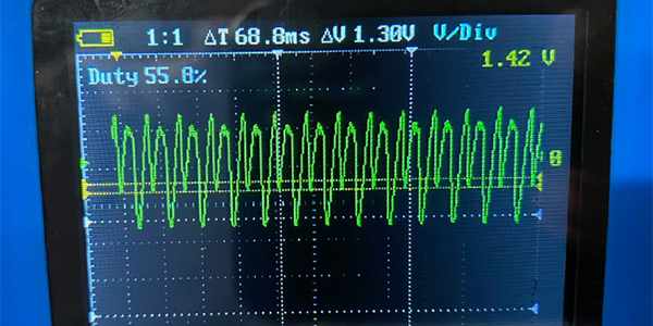
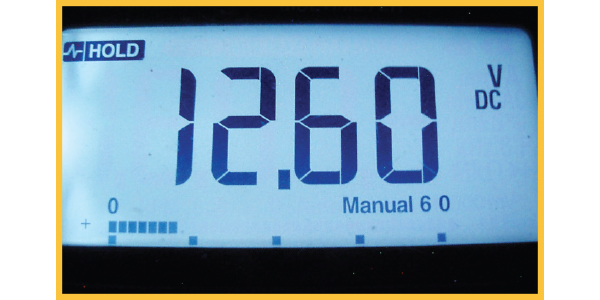
Now that we have a foundational knowledge of battery chemistry, let’s take a look at how computer-controlled charging systems might react to battery voltage and amperage flow. When a computer-controlled charging system senses 12.6 volts at the battery during idle conditions, it assumes the battery is fully charged and will usually take the alternator off-line (see Photo #1).
Since a defective battery cell prevents the battery from achieving the desired 12.6-voltage level, the alternator works harder to keep the battery fully charged. This tends to overheat the remaining battery cells, which produces a characteristic hydrogen sulfide or rotten egg odor.
An adjustable carbon pile load tester provides a definitive test for sulfated batteries. Accurate load testing requires the battery to be fully charged at a 70º battery core temperature. The battery is loaded to one-half of its rated cold-cranking amperage (CCA) for 15 seconds. At the end of the test, the battery should maintain at least 9.5 volts at its terminals.
VOLTS AND AMPS
In brief, voltage is the electrical potential or “pressure” existing inside an open circuit. Amperage can be described as the actual flow of electrons through a closed circuit. Given a constant circuit resistance, increasing voltage potential will also increase amperage flow. In effect, the ECM controls charging amperage by commanding the alternator’s internal voltage regulator to increase or decrease charging voltage.
STATE OF CHARGE
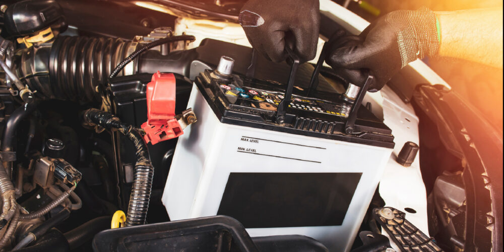
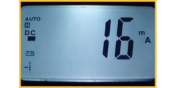
Each cell in a fully charged 12-volt battery produces 2.1 volts. Multiplying 2.1 volts times 6 cells = 12.6 volts, a number that should be committed to memory. Open-circuit voltage (OCV) is most accurately measured by disconnecting the negative cable from the vehicle or, as a second choice, testing the battery in an unloaded condition (see Photo #2).
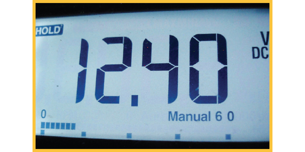
An OCV exceeding 12.6 volts is classified as “surface charge.” Surface charge can be quickly removed by turning on the headlamps or HVAC blower motor for five minutes. A battery discharged to 12.4 volts (see photo #3) will produce 60-70% of its rated cold-cranking capacity. A battery discharged to 12.0 volts generally won’t produce enough amperage to simultaneously crank the engine and operate the fuel and ignition systems, especially in cold weather. Any 12-volt battery that can’t reach the 12.6-volt threshold after an overnight charge usually has a bad cell or diluted electrolyte.
STATE OF HEALTH
Each day we’re moving closer to a full range of scan tool diagnostics that include the ECM’s estimation of battery state of health (SOH). In short, the ECM learns the normal voltage and amperage charging rates for a battery meeting the OEM cold cranking amp and reserve amperage specifications. As the battery ages, the ECM adjusts its charging algorithm to compensate for increased plate resistance in the battery.
For the long-term, the ECM can measure state of health by correlating volts and amps and charging times. On the one hand, a battery with a failing cell typically requires higher charging voltages and amperages as well as longer charging times to achieve the desired 12.6-volt threshold. On the other hand, if the battery is sulfated, charging voltages rise very quickly and amperage charging rates decline in a similarly short time. With these two basic failure patterns in mind, it’s easy to see how the ECM can measure current battery state of health and in many cases predict remaining battery life. So, don’t be surprised when you find “Battery SOH” appear as a data line on your scan tool’s diagnostic menu when diagnosing a modern charging system.
REPLACING A BATTERY IS MORE THAN JUST NUTS AND BOLTS
1) A battery in poor state of health will likely turn on the “battery warning” light.
2) If a voltmeter indicates 12.6 volts at the battery, the scan tool must indicate a similar voltage.
3) If, for example, the ECM data indicates 17.0 system volts, the ECM might disable the alternator because the ECM itself is incorrectly sensing battery voltage.
4) A replacement battery must meet the OEM’s specified cold-cranking amp and reserve capacity required by a vehicle’s computerized charging system.
5) When a battery is replaced, the ECM’s “learned” charging voltage levels will likely be too high for the new battery.
6) A scan tool must be used to “register” the new battery with the ECM by erasing the learned values contained in the charging system’s adaptive memory and resetting the battery monitor.
7) When sustained high charging amperages indicate a poor state of health for the battery, some ECMs are capable of setting DTCs for a battery malfunction.
8) Similarly, if a battery load sensor or voltage sensor fails, an appropriate diagnostic trouble code might be stored in the ECM’s diagnostic memory.
9) Some battery load sensors are also capable of measuring parasitic drain, which can greatly simplify battery diagnostics.
10) Since a computer does the thinking in any modern charging system, an enhanced or OEM scan tool will help you arrive at a successful diagnosis.