Applies To:
2001-’05 Civic 2/4-door – all
2002-’05 Civic 3-door – all
2003-’05 Civic Hybrid ULEV – all
2002-’04 CR-V – all
Symptom: The MIL comes on with DTC P1457 (EVAP control system leakage).
Probable Cause: The EVAP solenoid valve (fuel vent module) is blocked or restricted.
Corrective Action: Install an EVAP solenoid valve kit.
Parts Information:
EVAP Solenoid Valve Kit: Civic – P/N 06172-S5A-305, CR-V – P/N 06172-S9A-305
Fuel Tank Unit Locknut and Base Gasket: Civic VINs beginning with 1HF or JHM P/N 17046-S5A-A00, Civic VINs beginning with 2HG or SHH P/N 17046-S0X-A30, CR-V P/N 17406-S9A-A00
Fuel Feed Retainer: All models – P/N 17711-S84-004
Fuel Pulsation Damper Washer: CR-V only – P/N 16705-PD1-003
Propeller Shaft Bolts (eight required): CR-V 4WD only – P/N 90113-S10-000
Diagnosis:
1. Connect the HDS to the DLC (data link connector) and check for DTCs. Is DTC P1457 stored?
Yes – Clear the DTC, then go to step 2.
No – This service bulletin does not apply; continue with normal troubleshooting.
2. Follow the HDS screen prompts, and do the EVAP Function Test. Did the EVAP solenoid valve pass the test?
Yes – This service bulletin does not apply; continue with normal troubleshooting.
No – If you’re working on a Civic, go to Repair Procedure A. If you’re working on a CR-V, go to Repair Procedure B.
Repair Procedure A:
1. Relieve the fuel pressure.
2. Drain the fuel, then remove the fuel tank.
3. Remove the EVAP solenoid valve (see Fig. 1):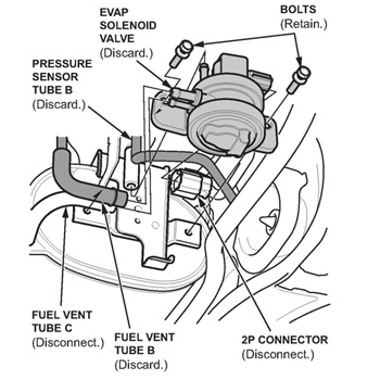
– Remove pressure sensor tube B; it will be reused.
– Remove fuel vent tube B; it will not be reused.
– Disconnect fuel vent tube C from the EVAP solenoid valve. The tube will be reused.
– Disconnect the 2P connector from the EVAP solenoid valve.
– Remove the EVAP solenoid valve (two bolts). The bolts will be reused. The valve will not be reused.
4. Attach the tubes and the joint from the kit onto the new EVAP solenoid valve as shown in Fig. 2. 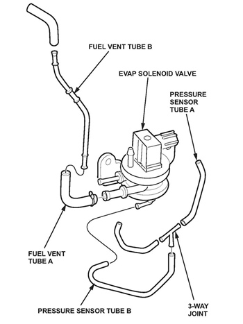
5. Install the new EVAP solenoid valve using the original bolts.
6. Connect the original hoses and the new tubes as shown in Fig. 3. 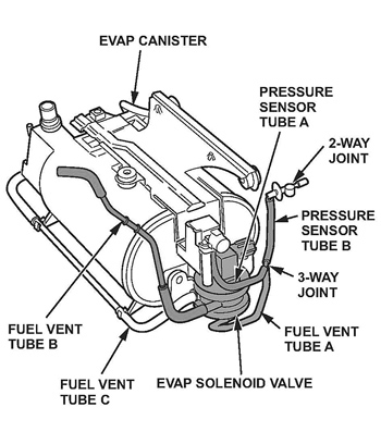
7. Reinstall the fuel tank.
8. Reinstall the fuel tank unit with a new base gasket and a new locknut.
9. Reinstall the fuel line to the tank with a new fuel feed retainer.
10. Refill the tank with the fuel you removed in step 2.
Repair Procedure B:
1. Relieve the fuel pressure.
2. Drain the fuel, then remove the fuel tank.
3. Remove the EVAP canister.
4. Remove the EVAP solenoid valve from the EVAP canister (see Fig. 4):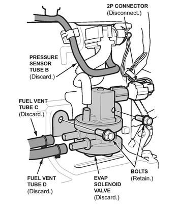
– Remove pressure sensor tube B; it will not be reused.
– Remove fuel vent tube C; it will not be reused.
– Remove fuel vent tube D; it will not be reused.
– Disconnect the 2P connector.
– Remove the EVAP solenoid valve bolts. The bolts will be reused.
– Disconnect the remaining hoses connected to the EVAP solenoid valve, then remove the valve. The valve will not be reused.
5. Attach the tubes, the vacuum chamber, the joint and the clips from the kit onto the new EVAP solenoid valve as shown in Fig. 5. 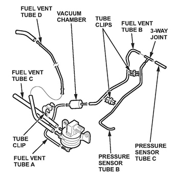
6. Install the new EVAP solenoid valve on the EVAP canister using the original bolts.
7. Reinstall the EVAP canister.
8. Connect the original hoses and the new tube as shown in Fig. 6. 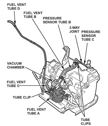
9. Reinstall the fuel tank.
10. Reinstall the fuel tank unit with a new base gasket and a new locknut.
11. Reinstall the fuel line to the tank with a new fuel feed retainer.
12. Refill the tank with the fuel you removed in step 2.
Courtesy of ALLDATA.