MAP/BARO VALUES
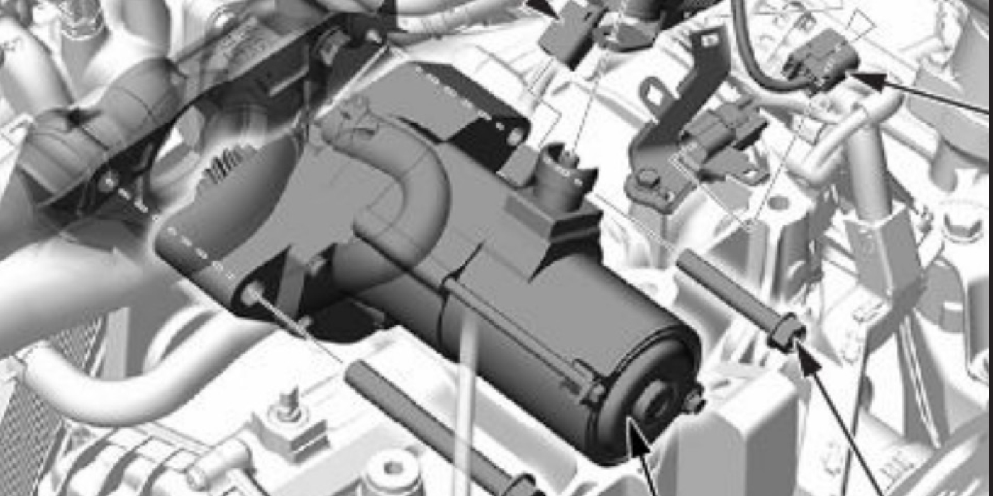
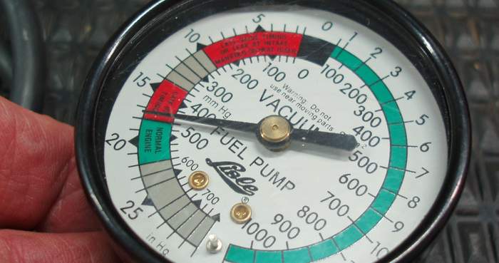
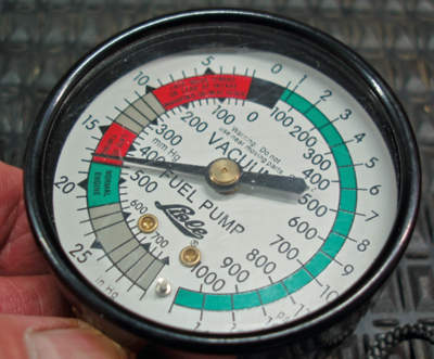
The MAP/Baro sensor reports the vehicle’s operating altitude (barometric pressure) to the ECM at key-on, engine-off (KOEO). While weather conditions and intake air temperature will modify the MAP/Baro reading somewhat, a typical KOEO baro is 29.5 inches of mercury (29.5” Hg) at slightly above sea level. At an altitude of 8,000 ft., a typical KOEO Baro is 22.5” Hg. See Photo 2.
At idle speed, the MAP/Baro reports manifold absolute pressure, which is the barometric pressure inside the intake manifold. MAP might be expressed on a scan tool datastream either as a pressure differential or as conventional intake manifold vacuum. At sea level, 29.5” Hg KOEO and 22.5” Hg key-on, engine-running (KOER) might be displayed as a -7.0” Hg pressure differential. Some scan tools might interpret that same data as +22.5” Hg “intake manifold vacuum.”
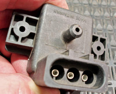
Because the new generation of engines will likely be turbocharged, MAP values will range well above atmospheric and, for that reason alone, it’s better to think in terms of MAP than vacuum. See Photo 3.
SPEED DENSITY
As a refresher on speed density diagnostics, remember that speed density and mass airflow (MAF) systems react oppositely to air leaks through the intake duct and manifold at closed throttle. Most MAF sensors are located at the air filter housing and are connected to the throttle body assembly by a flexible plastic duct. Air leaking through the intake duct or manifold will reduce airflow through the MAF sensor, causing the MAF sensor to underestimate the mass of air flowing into the engine.
This underestimation of airflow will cause a lean air/fuel condition, which is indicated by positive fuel trim numbers. In contrast to MAF systems, the speed density system is unaffected by air leakage upstream of the throttle body assembly. But air leakage downstream of the throttle body tends to increase barometric pressure inside the intake manifold, which can cause a rich air/fuel mixture ratio that will be indicated by negative fuel trim numbers.
If you’ve experimented with an older speed density system by attaching a vacuum pump to the MAP/Baro sensor vacuum line to make minor changes in the reported MAP values, you quickly realize how sensitive the engine’s fuel control system is to MAP. The speed density system’s ability to instantly respond to changes in air density downstream of the throttle plate is crucial for making fast and accurate air/fuel ratio calculations.
More important, when the engine is running, air density inside the intake manifold is partly controlled by throttle plate position.
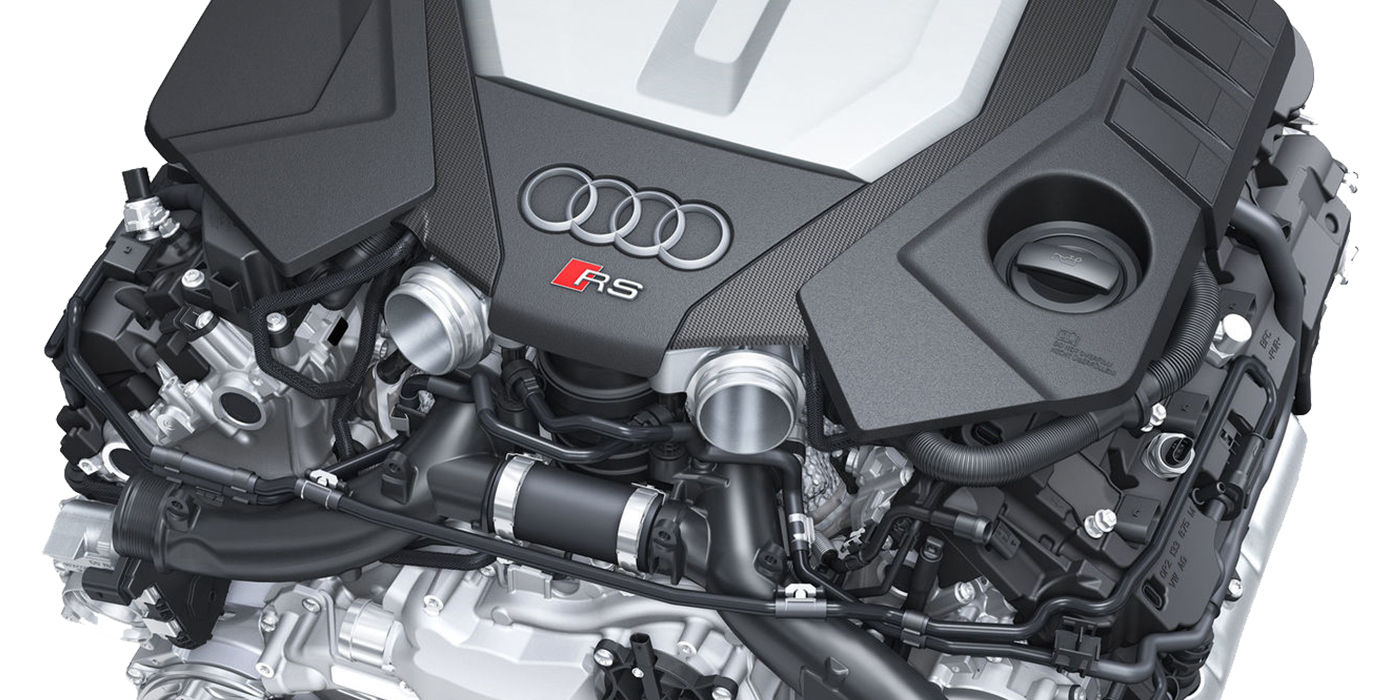
To illustrate, at wide-open throttle peak engine speed, MAP inside the intake manifold is nearly equal to the outside barometric pressure. At closed-throttle idle speed, MAP inside the intake manifold (ex. 22.5” Hg) is considerably less than barometric (29.5” Hg). At part throttle, MAP is largely dependent upon engine load. MAP pressure will become more equal to barometric as engine load is increased at a fixed throttle position.
In contrast, MAP pressure will become less equal to barometric as engine load is reduced at a fixed throttle position. With these issues in mind, we might catch a glimpse of why a modern turbocharged, variable-valve timing engine might be better served by a speed density system than a traditional mass airflow system. See Photo 4.