By Gary Goms
Contributing Editor
Confused about modern ride control technology? Sometimes looking back into automotive history can put such technology into a more usable framework. A good illustration is how ride control technology evolved from the simple, early-century friction shock absorber to the electronic variable-rate shocks and MacPherson struts currently being installed on late-model imports.
When early automobile manufacturers first mated a gasoline engine to what was essentially a buggy chassis, they quickly discovered that the buggy-style suspensions with high percentages of unsprung weight concentrated in the wheels and axles would bounce uncontrollably at anything above horse-drawn speeds. As speeds increased, the need for a spring dampening device or “shock absorber” became apparent and what we now refer to as the “ride control industry” was born.
EARLY RIDE CONTROL TECHNOLOGY
The first shock absorbers were simply pieces of leather or asbestos sandwiched between spring-loaded plates, with the friction body mounted to the chassis and a movable arm attached to the axle. As the suspension moved up and down in relation to the chassis, the friction shock dampened the resulting spring oscillations by converting excessive spring oscillations into heat. Unfortunately, overheating would reduce the efficiency of the friction shock during sustained high-speed driving conditions.
The tubular, oil-filled “airplane” shock absorber, popularly introduced in the 1930s, seemed to offer the best solution for good ride control. At its most basic level, the tubular shock contains a piston that slides back and forth in a steel cylinder filled with oil. To create a dampening action, small orifices are drilled into the piston, which allow a restricted amount of oil to flow from one side of the piston to the other. Check valves are also added to the piston holes to vary the ratio of force needed to extend or compress the shock absorber.
Needless to say, the oil-filled tubular shock absorber proved that it could dampen spring rebound throughout a wide range of driving conditions by maintaining a specific extension-compression ratio and by dissipating heat much more efficiently than its friction counterpart.
PERFORMANCE TECHNOLOGY
The basic idea behind any performance suspension system is to keep the tire in contact with the road surface. Like the modern import vehicle, the unsprung weight of the wheel, brake and axle of a modern racing vehicle has been reduced to a minimum. Spring rates have been refined to provide instant response to changes in chassis height. In addition, tire design and operating pressures have become a critical part of ride control because the tire itself acts as part of the spring package by absorbing a degree of minor road surface irregularities.
As for the shock absorber, remember that its firmness, and the ratio of its compression and extension rates, are extremely important in maintaining tire contact with the track surface. If the shock is too firm, the wheel will tend to loft the chassis because the suspension has become too rigid to respond to minor surface irregularities in the road. If the shock is too soft, a major surface irregularity will lose contact with the road surface by lofting the wheel off the pavement.
Compression-to-extension ratios are similarly important in any shock absorber. To better absorb the upward thrust of bumps, the shock’s resistance to compression is less than its resistance to extension. The extension force is high to prevent the spring from slamming an airborne wheel against the road and causing still another rebound cycle.
In racing applications, a shock’s firmness and compression/extension ratios are “tuned” according to the severity of the track surface, spring rates and tire pressures. Off-road racing, for example, requires a shock absorber with “soft” valving that will instantly absorb huge undulations in the road surface. Off-road shocks also are designed to permit large amounts of suspension travel, and be installed in multiple shock installations on each wheel to better dissipate heat during a long-distance race.
MODERN RIDE CONTROL TECHNOLOGY
Modern shock absorber design follows all of these design considerations. For example, the aspect or sidewall height-to-tread width ratio of a tire affects the valving required to create a smooth ride or better handling in a vehicle. In addition, the suspension travel available in the suspension and the types of road surfaces that the vehicle may traverse also has a direct effect on shock absorber design.
To meet these various demands, some ride control manufacturers have “tuned” shock absorbers by designing valving that increases firmness as the shock reaches full compression or extension. These shocks permit a comfortable ride while providing good dampening at the extremes of the shock absorber travel. Shock absorber manufacturers further dampen road shock by charging shock absorbers with nitrogen to reduce oil foaming and by increasing oil capacity to help dissipate heat from the shock absorber oil.
WEAR INDICATORS
No doubt you’ve been driving on the freeway at high speed and saw a vehicle in the next lane with a wheel bouncing erratically over rough pavement. Of course, while wheel bounce can be aggravated by poor tire balance, the primary cause is a shock absorber that’s become overheated due to a low oil level, caused by a leaking shaft seal and by high oil temperatures aggravated by excessive wear in the piston assembly.
It’s important to understand that worn shocks can’t always be detected with the vehicle resting in the service bay. During a rebound test, a good shock absorber should arrest suspension travel by its second rebound. However, if oil is leaking around the shaft seal, it may indicate that the shock will overheat and fail under extended operation.
The most apparent symptom of overheating and loss of rebound control is a cupping pattern along the center of the tread that can be felt by lightly stroking the fingertips around the circumference of the tire. Another indicator of a worn or defective shock absorber is a chucking or knocking noise as the suspension is rebound-tested in the shop. In most cases, the chucking noise is caused by loose shaft bushings or a piston coming loose from the shaft itself.
As a technician develops a familiarity with the suspension systems found in different nameplates, he’ll find that it becomes much easier to distinguish when the shock absorbers are reaching the end of their service life. For example, driving over a small bump or speed ditch in a parking lot may loft the body more than usual. Similarly, a low-speed panic stop or turning a sharp corner may reveal body pitch or roll characteristics that are unusual for a particular vehicle platform. In either case, the technician should follow up with a visual inspection and service recommendation for his customer.
ACTIVE SUSPENSION SYSTEMS
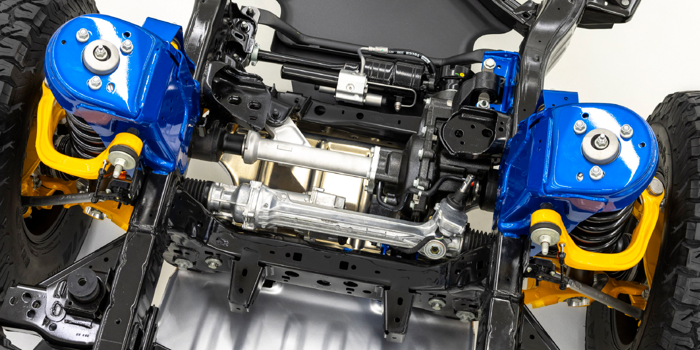
Of course, electronically controlled shock absorber valving is currently being employed in many imports with active suspension systems. Even more important, some OEMs are electronically tuning or adjusting their suspension systems to reduce body roll during cornering and body pitch during rapid braking.
In any case, whether electronic or conventional, any ride control device eventually wears out or becomes damaged through collision or extreme operating conditions. As always, paying attention to the difference between the normal and abnormal dampening characteristics of any ride control device is the key element in making a ride control service recommendation.
Goms owns Midland Engine Electronics & Diagnostics in Buena Vista, CO. He is an ASE-certified Master Auto Technician, ASE L-1 Advanced Engine Performance Technician, and specializes in performance-related diagnostic issues.

