Most TPMS sensors are held in using just a screw or a nut, but if not assembled or torqued properly, the results can be catastrophic. Carelessness can result in a broken sensor or even a customer being stranded with a flat tire.
The torque tools required to install TPMS sensors include:
- Torque wrench that measures torque in inch-pounds;
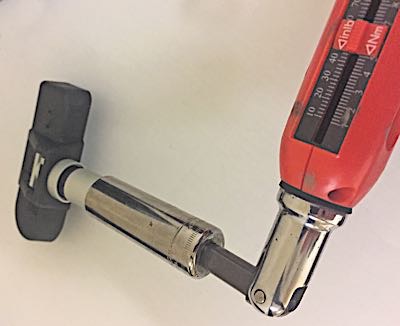
- Preset torque-calibrated T10 screwdriver; and
- Preset torque valve stem torque tool.
Clamp-on Sensors
Anytime a clamp-on TPMS sensor is reused or replaced on a wheel, it is necessary to install new seals and valve stem nuts to ensure proper sealing around the sensor valve stem.
1. Wipe the area clean around the sensor/valve stem mounting hole in the wheel. Make sure the surface of the wheel is not damaged. Pieces of the old seal can cause a slow leak. Do not lubricate or use a sealant in this area. This can change the torque values and cause you to snap the stem.
2. If the valve core is removed, it must be replaced with a new valve core in order to avoid galvanic corrosion issues, which may cause the valve core to fail.
3. Insert the sensor through the wheel, keeping pressure against the rear of the metal valve stem. The potted side of the sensor is to be positioned toward the wheel. Mounting the sensor upside down can cause relearn and transmission problems. The two grommets seal the sensor and nut to the wheel.
Grommets conform to the mating surface of the wheel. The instant the nut is torqued, the seal/grommet starts to take on the shape of the surfaces it is sealing against. This memory cannot be erased. If the seal is reused, it could cause a slow leak.
Never reuse these nuts. The nut is made of a softer metal than the stem, so it can be damaged or develop hairline cracks if it is over-tightened. The material of choice is typically aluminum. The new nut may have coatings on the threads that prevent corrosion and leaks.
Before tightening the sensor nut, push downward on the sensor housing in an attempt to make it flush with the interior contour of the wheel. Some clamp-in stems have the ability to change the angle of the sensor by loosening a fastener that holds the sensor on the stem. Other sensors should assume the correct position when the nut is torqued.
4. While holding the sensor in position, tighten the sensor nut with a torque wrench. Typical torque values for the base nuts on a TPMS valve stem range from as low as 35 in.-lbs. of torque to as much as 80 in.-lbs. of torque. That’s quite a range. This does not mean that any torque value within this range is acceptable. It means that the torque specifications for the base nut on one car might require 44 in.-lbs., another might require exactly 62 in.-lbs., another might specify exactly 71 in.-lbs., and so on. Don’t guess. Look up the torque specifications for the vehicle you are servicing to make sure you use the correct torque. Over-torquing the sensor nut by as little as 12 Nm (106 in.-lbs.) may result in sensor separation from the valve stem.
Leaks cannot be eliminated by tightening the nut more. Sealing grommets are engineered to work at a specific torque. Any torque above the specified value will cause the seal to leak. Extra force may also damage the nut or valve stem or fracture the sensor body.
5. Mount the tire on the wheel following the tire changer manufacturer’s instructions, paying special attention not to damage the tire pressure sensor.
Snap-in Sensor Installation
Snap-in sensors can look like regular rubber valve stems. The difference is that the molded rubber on the snap-in valve stem does not reach the threads and there is a tapered shoulder. These valves have a longer cap than a non-TPMS valve stem.
Behind the stem is a mounting point for a self-tapping screw that holds the sensor to the stem. There are two installation methods depending on the type of snap-in valve stem you are installing. Always check the instructions or the manufacturer’s recommendation.
The first method is installing the valve stem in the rim and then attaching the sensor. The second method is to attach the sensor to the valve stem and then insert it into the wheel. Why? On some stems, the sensor could come in contact with the wheel as the stem is pulled with the sensor attached.
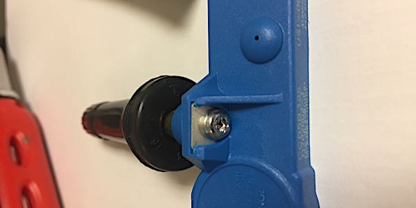
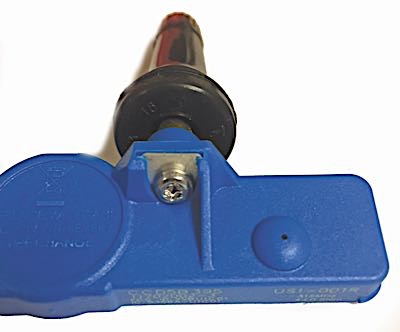
When attaching a new valve to the sensor body, always use a preset torque screwdriver with the correct torx head or hex nut. Most tool suppliers package two preset torque drivers in a set. The torque settings may differ by manufacturer. The screw is self-tapping and can be used only once. The same applies to the stem.
When tightening the screw, be mindful of stress on the sensor and the alignment of the sensor. Start the screw for the first couple of threads and make sure the sensor and stem are aligned. When performing the final tightening sequence, stop when the tool clicks, which indicates that the proper torque has been reached.
Before installing the valve stem, it is acceptable to lubricate the seating surfaces with an approved tire lubricant. Do not use chassis grease or a grease with petroleum distillates. These types of lubricants can degrade the stem over time and cause a leak. Lubricating the stem can help in the alignment of the sensor on the flats.
When using a tire valve stem installation tool, pull the valve stem straight through the valve hole rather than at an angle.
Some valve stems have a tab on the body of the valve that can help in the alignment of the sensor. For most applications, the rubber bulb of the valve should be resting against the rim and the sensor body should not be touching the rim.