Nothing is more frustrating than diagnosing an intermittent cranking, no-start complaint with no diagnostic trouble codes (DTCs) and no apparent failure pattern. Much of the time, the cranking, no-start complaint lies with a failing crankshaft or camshaft position sensor. Many of these failures can be heat-related and might require several warm-up cycles to duplicate.
So, in some instances, it’s more economical to replace a crankshaft or camshaft position sensor than it is to spend hours trying to capture the suspected failure on a scan tool or lab scope.
In other instances, the failure lies within the wiring harness or, in some cases, the ignition control module (ICM) or the powertrain control module (PCM). Whatever the case, a technician needs a good working knowledge of how the camshaft and crankshaft position sensors work together to create a fuel injection and spark cycle.
CRANKSHAFT POSITION SENSORS (CKP)
In brief, the crankshaft position sensor (CKP) indicates when each piston reaches top dead center (TDC). To time the spark event, the PCM calculates the angular position of the crankshaft connecting rod journal in relation to TDC. To illustrate, the PCM might time the spark event at 10° before top dead center (BTDC) on the compression stroke. See Photo 1. 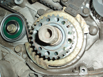
The CKP also detects cylinder misfires on post-1996 OBD II engines by measuring very small variations in crankshaft speed. For example, the crankshaft decelerates as a cylinder approaches TDC on compression stroke. After combustion, the crankshaft accelerates on the power stroke until about 90° after top dead center (ATDC), when cylinder pressure is expended and the angularity of the connecting rod diminishes. When this very predictable deceleration and acceleration pattern is disrupted on a continuing basis, the PCM stores a misfire trouble code for that cylinder.
CAMSHAFT POSITION SENSORS (CMP)
Because the crankshaft on a four-cycle engine rotates at twice the speed of the camshaft, each cylinder fires on alternate strokes. In most applications, the CMP determines when number-one cylinder reaches TDC on compression stroke. With that said, some engines don’t incorporate a CMP into their operating strategy. Instead, the PCM alternates base timing 180° during cranking and, when an increase in cranking speed is detected, the PCM identifies that position as TDC compression stroke. See Photo 2.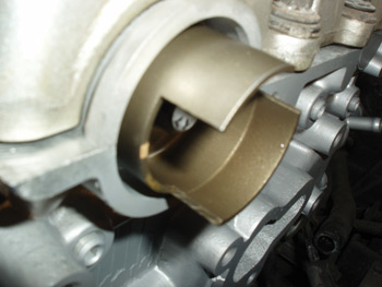
The basic function of the CMP, in most applications, is to determine when fuel should be injected into the cylinder. In most applications, the injector sprays fuel into the intake port at about 26° ATDC when the intake valve is nearing maximum lift.
DISTRIBUTOR IGNITIONS
Some import distributors might incorporate a crankshaft, camshaft and TDC position sensor to allow the sequential fuel injection system to sense TDC compression stroke. Because the integrated camshaft position sensor can be used to time the fuel injection, it’s important to install the number-one spark plug wire in its specified position and to install the distributor and rotor in their specified positions. See Photo 3.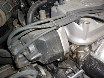
MAGNETIC RELUCTANCE POSITION SENSORS
The magnetic reluctance sensor is basically a single wire wrapped around a permanent magnet, with each end of the wire representing a positive or negative pole. As a rotating ferrous reluctor tooth passes the sensor, it generates an alternating current (AC) signal to the PCM.
In Photo 4, notice that the “analog” signal varies between approximately 0.8 positive volts and 0.2 negative volts. Because AC voltage can be displayed more accurately on a lab scope than a voltmeter, it’s easier to track the voltage as it alternates between positive and negative. In this case, the PCM “reads” TDC when the sensor signal crosses the zero volt line. The accuracy of the reluctance sensor varies slightly due to the voltage switching from positive to negative at slightly different points along the “zero” line. The accuracy of the reluctance sensor can also be affected by the sensor magnet attracting particles of ferrous material from clutch linings or wearing parts. 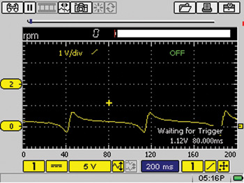
In most applications, the reluctor for the number-one cylinder is slightly modified to provide a “signature” waveform indicating to the PCM when that cylinder reaches TDC. When diagnosing a magnetic reluctance sensor, it’s extremely important to remember that voltage output or amplitude depends very much on the air gap between the sensor tip and reluctor and the speed of the reluctor.
HALL EFFECT POSITION SENSORS
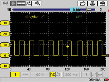
Hall effect sensors are generally three-wire sensors that produce a square-wave digital signal that is sent to the ICM or PCM. See Photo 5.