Since Hall effect sensors are produced in many different configurations, suffice it to say that the Hall effect sensor acts as an electric switch that requires an outside power source and a ground to produce the square-wave, on-off pattern. Unlike magnetic reluctance sensors, Hall effect sensors don’t rely on shaft speed to generate a signal.
CKP QUICK TESTING
Scan tools provide the best non-invasive method for diagnosing a cranking, no-start condition. If, for example, engine rpm or speed is displayed during cranking, it’s obvious that the CKP is producing a valid signal. In other cases, the software in the PCM or in the scan tool might not allow the engine speed to be displayed as the engine is cranked.
Another quick, non-invasive test for CKP activity is to connect a voltmeter to the B- side of the ignition coil. If the voltage pulls down from B+ during cranking, the CKP is triggering the ignition module or PCM. If the CKP isn’t triggering spark, the fault might lie with the CKP, ICM or PCM circuits.
CAMSHAFT TIMING SENSORS
In addition to the CMP, most engines equipped with variable camshaft timing incorporate a camshaft timing sensor that indicates the degree of advance or retard being adjusted into the camshaft. Don’t confuse the two because a defective timing sensor generally shouldn’t cause a cranking, no-start complaint and should only store a diagnostic trouble code if it fails.
CMP QUICK TESTING
While some PCMs won’t fire the fuel injectors without a CMP signal, other PCMs adopt a default strategy for firing the fuel injectors if the CMP signal is erratic or missing. In most cases, if the engine has spark, but the fuel injectors aren’t triggering, the CMP signal is missing. See Photo 6.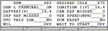
DO YOUR HOMEWORK
Before attempting to diagnose CKP and CMP circuits with a voltmeter or lab scope, try to understand how the system works by having the required wiring schematics on hand. To illustrate, most CKP circuits are wired directly to the PCM.
But, if the ignition takes place through an ICM, the CKP is normally wired directly to the module.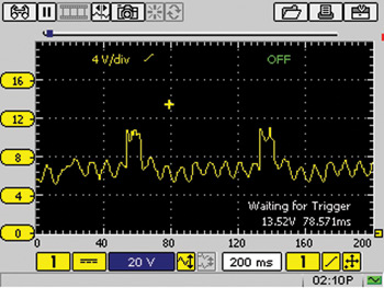
Some ICMs receive a digital signal from a Hall effect CKP sensor and relay that signal to the PCM. Other ICMs convert the analog signal from a reluctance-type CKP sensor to a digital signal before relaying it to the PCM. Once the engine has started, the PCM advances spark by modifying the CKP signal and returning it to the ICM as an electronic spark timing signal.
Here’s an interesting analog or sine wave I captured that 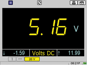 includes the signature signal. See Photo 7. The EST signal sent from the ICM to the PCM is equally as bad. See Photo 8.
Needless to say, the CKP signal from the reluctor-type sensor is floating well above zero volts, which indicates that the ICM might have a bad ground. See Photo 9.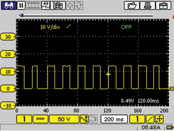
PHYSICAL INSPECTIONS
After preliminary testing, the next step in diagnosing intermittent crankshaft and camshaft position sensor performance is to physically inspect them for loose, chafed or broken wires, loose connectors or loose mounting screws, or indications of damage.
Next, inspect the sensor itself for indications of swelling or cranking in the plastic.
Last, inspect the reluctor or Hall effect shutter for damage or looseness on the shaft. If no other failure conditions are found in the wiring or at the sensor or PCM, it’s entirely appropriate to replace either the CKP or CMP to remedy an intermittent, no-cranking complaint.