Most steering systems you will see in your bays are sealed. But, this does not mean that they do not need to be diagnosed, serviced or replaced. The most important thing to effectively accomplish this is to understand what is going on inside the steering box or rack.
You may think the diagnosis of a steering gear may be an inspection of free play, steering wheel effort and visual inspection. But it is a lot more than that if you are going to perform a job that will not have a comeback.
Conventional vs. Rack and Pinion
From the 1950s to the 1980s, the conventional recirculating ball steering gear was the dominant system. The 1980s saw the introduction of the front-wheel-drive passenger car with rack and pinion steering. This was due to packaging and not having to work around an oil pan with a drag link. Rack and pinion systems also weigh less and use fewer parts. Also, the manufacturers were able to bring the cost of rack and pinion systems down due to increased automation in the final machining process.
Today, most passenger cars and light trucks are equipped with rack and pinion steering. In February of this year, R. L. Polk & Co. placed the median age of passenger cars in operation at 9.2 years in 2007 tying a record high in 2006. This statistic says that there are significant numbers of conventional systems in operation and they will need service or will need replaced.
The designs of both systems are changing to used less hydraulic assist to reduce drag on the engine.
Conventional 101 Steering Linkage and Component Stack Up
Today’s conventional steering gear is a rack and pinion gear in reverse. The difference is the friction reducing ball nut and screw that converts the rotation of the steering wheel into the longitudinal movement of a rack gear attached to the ball nut.
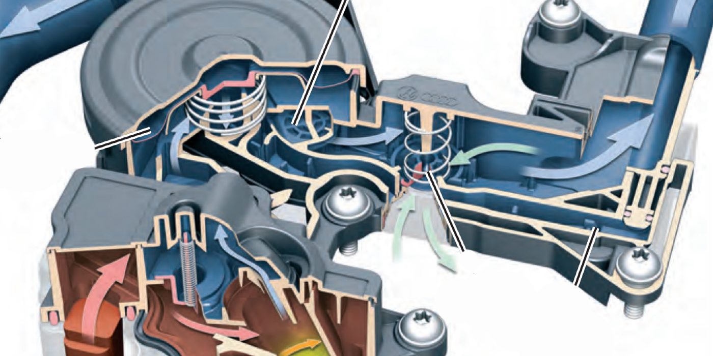
 The pinion is called the sector and is rotated by the rack. Most systems use a torsion bar and rotary valve to supply hydraulic pressure to the power piston that is part of the ball nut and screw assembly (Figure 1).
Attached to the sector is the pitman arm. The pitman arm moves in an arc and is connected to a series of linkages.
Independent front suspension passenger cars and light trucks use a power assist steering gear, idler arm, center link and tie rods to connect the steering gear to the steering knuckle. The pitman arm and the idler arms are fixed to move in a lateral plane. The pitman and idler arm are connected to the center link with fixed joints. This allows the center link to move in a lateral plane. The center link moves the tie rods to steer the vehicle. The tie rods are attached the center link and steering knuckle with ball and socket joints. This makes a total of four ball and socket joints and four fixed joints (Figure 2).
Conventional Steering Gear Inspection
The best way to inspect the steering system is with the vehicle on the ground or on the turn plates of an alignment rack. The inspection should begin with the pitman and idler arms. They should remain in the same plane as the wheels are turned from lock to lock.
In the case of the Chevrolet Astro and GMC Safari vans, the same applies to a drag link connected to the center link that has two idler arms. Some idler arms have a specified endplay that is measured with a spring tension gauge. Next is the steering gear. Check for leaks at the sector shaft. If these components are OK, check the play in the steering wheel.
Both the worm and sector and recirculating ball gears have a thrust adjusting screw. A rule of thumb says that there should be one to two inches of free play in the steering wheel and no binding when the wheel is turned from full lock to lock.
The thrust adjusting screw is located above the sector. Adjusting the screw can change the amount of free play in the steering gear. It is important to follow the recommended adjustment procedures, as some gears cannot be adjusted in the vehicle. If a recirculating ball steering gear is worn or has an internal problem, the safest approach is to replace the steering box with a warranted remanufactured gear.
The disadvantage of a conventional steering gear system is its complexity and the points where play can stack up. Excluding the steering gear, there are seven isolated wear points that are sealed and lubricated. If each joint has 0.020” play, it would equal 0.140 inch. The combined tolerances of each joint stacks up, which is more than 1/8 inch play in the linkage.
 Rack and Pinion 101
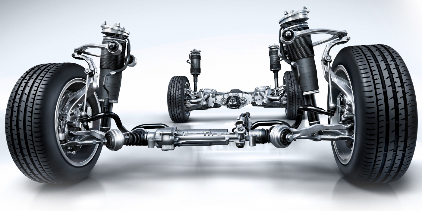
A rack and pinion steering gear uses a pinion gear to convert the rotation of the steering wheel into the lateral movement of the rack gear. The tie rods are attached to the ends of the rack with a ball and socket and conventional tie rod end connected to the steering knuckle. This reduces the number of ball and joint connections to four. The hydraulic power assist piston is located in the center of the rack with the tie rods attached using a threaded end to hold the ball and socket joint (Figure 3). A variation of the rack and pinion steering gear is the center take off. The tie rods are attached to the center of the rack and the power assist cylinder is moved to the end of the rack.
 The tie rods are designed with extended length to reduce the amount of bump and roll steer. The pinion gear is adjusted by a support that rides on the rack below the pinion gear (Figure 4). It has the same function as the thrust screw for a worm and sector or ball nut and sector. Most of the supports are preloaded with a spring. It is recommended to use the manufacturer’s adjustment procedure to ensure the proper preload on the rack.
Rack and Pinion Inspection
Some are manual, but most are power assist. Inspect the boots and pinion seal for leaks. If it is leaking or has an internal problem, the safest approach is to replace the gear with a new or remanufactured gear.
The tie rods are directly connected to the rack gear assembly. A ball joint connects the tie rod to the rack and a tire rod end, which is also a ball joint that attaches to the steering knuckle. These applications require a special tool to remove the ball joint from the rack without damaging a seal on the power cylinder. The center take off steering gear uses rubber bushings to attach the tie rods to the center of the rack housing.
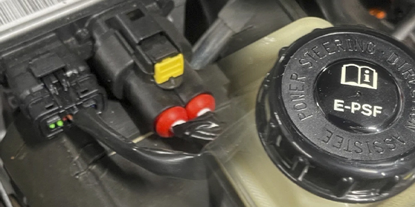
Electronic Power Steering (EPS) will most probably replace the current hydraulic power steering on most vehicles. The transition from hydraulic assist to electric motor assist will provide the driver with a more positive feel and control throughout the entire speed range of the vehicle. EPS system eliminates  the need for a pump, hoses and a drive belt connected to the engine using variable amounts of power. The configuration of an EPS system can allow the entire power assist system to be packaged on the rack and pinion steering gear or in the steering column. The steering system is more energy efficient.
A sensor is located in the steering column to measure steering wheel position and speed. A second sensor is located on the torsion bar of the motor assembly to measure torque or steering effort input to the steering wheel (Figure 5). The controller process the steering effort, wheel position and speed inputs with a series of software programs called algorithms to produce the polarity and current flow to the motor. The steering wheel can be referred to as a hand wheel in service information. The inputs from the steering controller are also shared on the Controller Area Network (CAN) buss. These inputs will affect other chassis control systems such as Anti-Lock Brakes (ABS) and Electronic Stability Control (ESC). As the requirements for vehicle stability controls move forward, the steering system will become an integral part of the braking and stability control program. This will mean more trouble codes and diagnostics.
Even the most advanced systems for the 2009 model year do not have trouble codes for worn gears, tie-rods or bent parts. It is up to you to make the right call on service.