I made a mistake probably because of my distaste of math, now it is time to learn from it. In a three-part series, we will look at the math of brakes. We will start with the driver pushing the brake pedal and end with the pad contacting the rotor and bringing the car to a stop. Along the way, we will explore the math of boosters, quick take-up master cylinders and caliper sizing.
On a mechanical level, it is easy to understand how brakes work. We all understand that brake fluid transfers force from one hydraulic component to another. But, how does this apply to how a brake pedal feels? This is where math is required.
You need only two simple math equations to commit to memory. First, the equation for calculating the surface area of a circle (caliper or master cylinder piston) is p(3.14) x radius2. Second, pressure is equal to the force divide by the area or pounds per square inch. The rest of the math is just multiplication, division and addition/subtraction.
Pedal Ratio
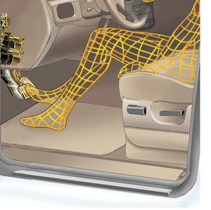
Lets start with the driver. In a sitting position, the average driver can comfortably generate 70 lbs. of force on the rubber pad at the end of the brake pedal. The brake pedal is nothing more than a
mechanical lever that amplifies the force of the driver. This is where the pedal ratio comes into play.
Pedal ratio is the overall pedal length or distance from the pedal pivot to the center of the pedal pad divided by the distance from to the pivot point to where the push rod connects.
The optimal pedal ratio is 6.2:1 on a disc/drum vehicle without vacuum or other assist method. This means that the 70 lbs. the driver has applied now is amplified to 434 lbs. (6.2 x 70 lbs.) of output force. The problem is that the travel of the pedal is rather long due to the placement pivot point and master cylinder connection.
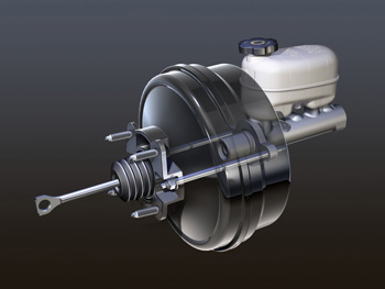
Brake Boosters
A booster increases the force of the pedal so lower mechanical pedal ratio can be used. A lower ratio can give shortened pedal travel and better modulation. Most vacuum boosted vehicles will have a 3.2:1 to 4:1 mechanical pedal ratio.
The size of the booster’s diaphragm and amount of vacuum generated by the engine, will determine how much force can be generated. Most engines will generate around -8 psi of vacuum (do not confuse with inches of HG or Mercury). If a hypothetical booster with 7-inch diaphragm is subjected to -8 psi of engine vacuum, it will produce more than 300 lbs. of addition force. Here is the math:
π(3.14) X radius(3.5)2 = 38.46 sq/inches of diaphragm surface area X 8 psi (negative pressure becomes positive force)= 307.72 lbs of output force
To keep things simple, let’s return to our manual brake example. The rod coming from the firewall has 434 lbs. of output force. When the force is applied to the back of the master cylinder, the force is transferred into the brake fluid.
The formula for pressure is force divided by the surface area.
If the master cylinder has a 1-inch bore, the piston’s surface area is .78 square inches. If you divide the output force of 434 lbs. by the surface area of the piston, you would get 556 psi(434 lbs. divided by .78 inches) at the ports of the master cylinder. Not bad for a 70 lbs. of human effort.
If you reduce the surface area of the piston you, will get more pressure.
This is because the surface area is smaller, but the output force from the pedal stays the same. If you used a master cylinder with a bore of .75 inches that has a piston that has .44 inches of piston surface area, you would get 986 psi at the ports for the master cylinder (434 lbs. divided by .44 inches).
But, how is this force transferred to the calipers? How does the size of the caliper piston change the force needed to push the brake pad to the rotor? We will explore this next month.