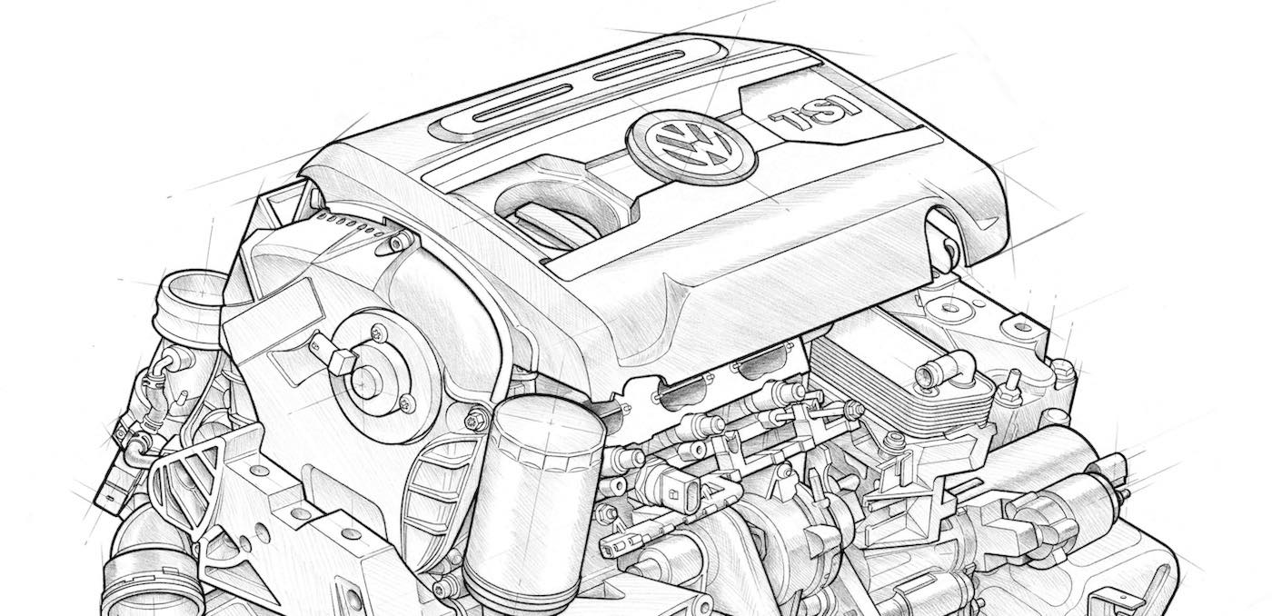
The 2.0T TSI engine can be found under the hood of a number of VW models including the Golf, the New Beetle, Jetta, Passat, and more. As with every mass-produced engine, they are not without a few common issues which your customers may experience from time to time. We’re going to focus our attention on the runner flaps which are located inside the intake manifold, which DTCs may be stored in the ECU, and what you need to know in order to repair the issue.
Manifold Construction
The intake manifold is composed of two polyamide shells which are plastic-welded together (Figure 1). Trough-shaped flaps, also known as tumble valves, can be found inside each intake port. A potentiometer is used to measure the flap position (Intake Manifold Runner Position Sensor – G336). The flaps are closed when the engine is not running and will open only after a number of prerequisites have been met.
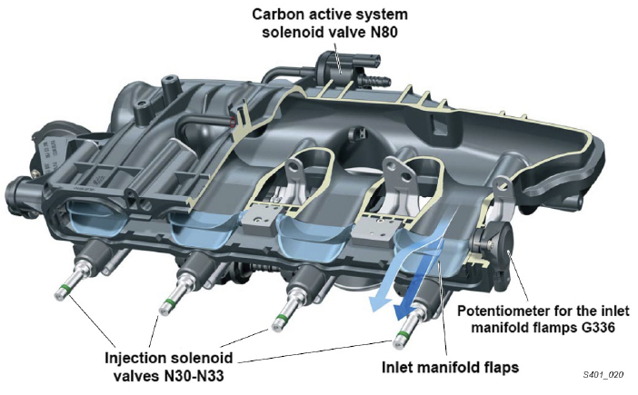
Vacuum is applied to the actuator to cycle the tumble valves open or closed. Herein lies the weak point of the system, the plastic linkage. If the flaps were to become stuck due to carbon buildup, then the plastic linkage can easily bind up and snap. This linkage is not serviceable separately, so the entire manifold needs to be replaced. These issues were so common that later production units were revised with more robust linkage for improved durability.
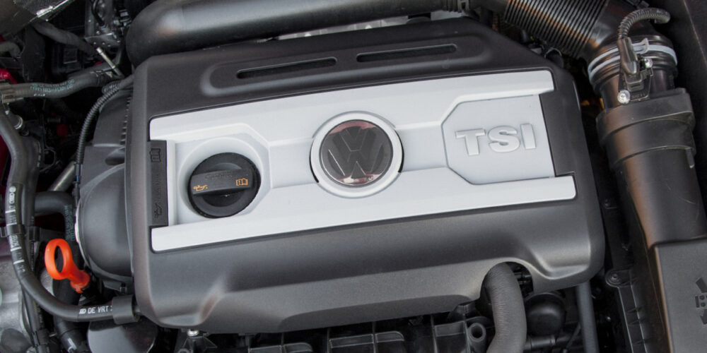
It’s worth noting that there are two different generations of the 4-cylinder TSI engine here in the US market: the Gen1 and Gen3. How do you tell the difference? It’s all in the oil filler cap and oil filter. If you see the oil filler cap on top of the valve cover and a metal spin-on oil filter next to the intake manifold, you’re looking at a Gen1 TSI engine. If the oil filler cap is on the timing cover, and there is a plastic oil filter housing cap next to the intake manifold, you’re looking at a Gen3 TSI engine. It’s important to know the difference between these engines because the Gen3 engines don’t seem to suffer from the same intake manifold issues.
Common DTCs
If your customer brings a vehicle into your shop with these issues, chances are good that you’ll find one of three codes stored in the ECU memory:
• P2004: Intake manifold flap for air flow control bank 1 stuck closed.
• P2014: Intake manifold runner position sensor/switch circuit.
• P2015: Intake manifold runner position sensor/switch circuit range/ performance.
You may find other codes which point to a lean fuel mixture. If you see this, be sure to check the area around the linkage arm on the side of the manifold and see if it has popped out. Since the linkage arm is located past the throttle body, it will create a large air leak which will lean out the fuel mixture, and may also cause other drivability concerns.
No matter what fails inside the manifold, the entire unit needs to be replaced. This isn’t uncommon these days as vehicle components continue to become more modular. I remember something that one of my first shop mentors taught me: “vehicles are designed to be assembled, not worked on.” Automakers try to engineer their vehicles so that they can roll down the assembly line as quickly and efficiently as possible. Sometimes that helps us as techs, sometimes it hinders us. But I don’t see this changing any time soon.
Tips & Tricks
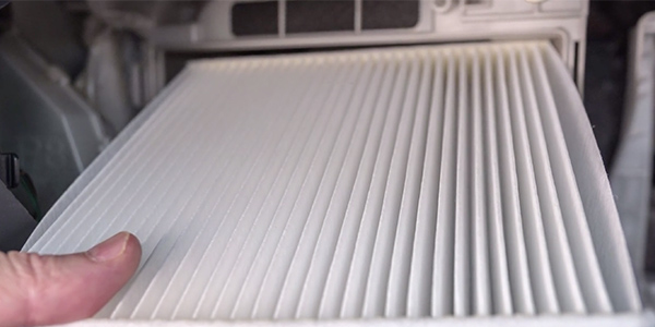
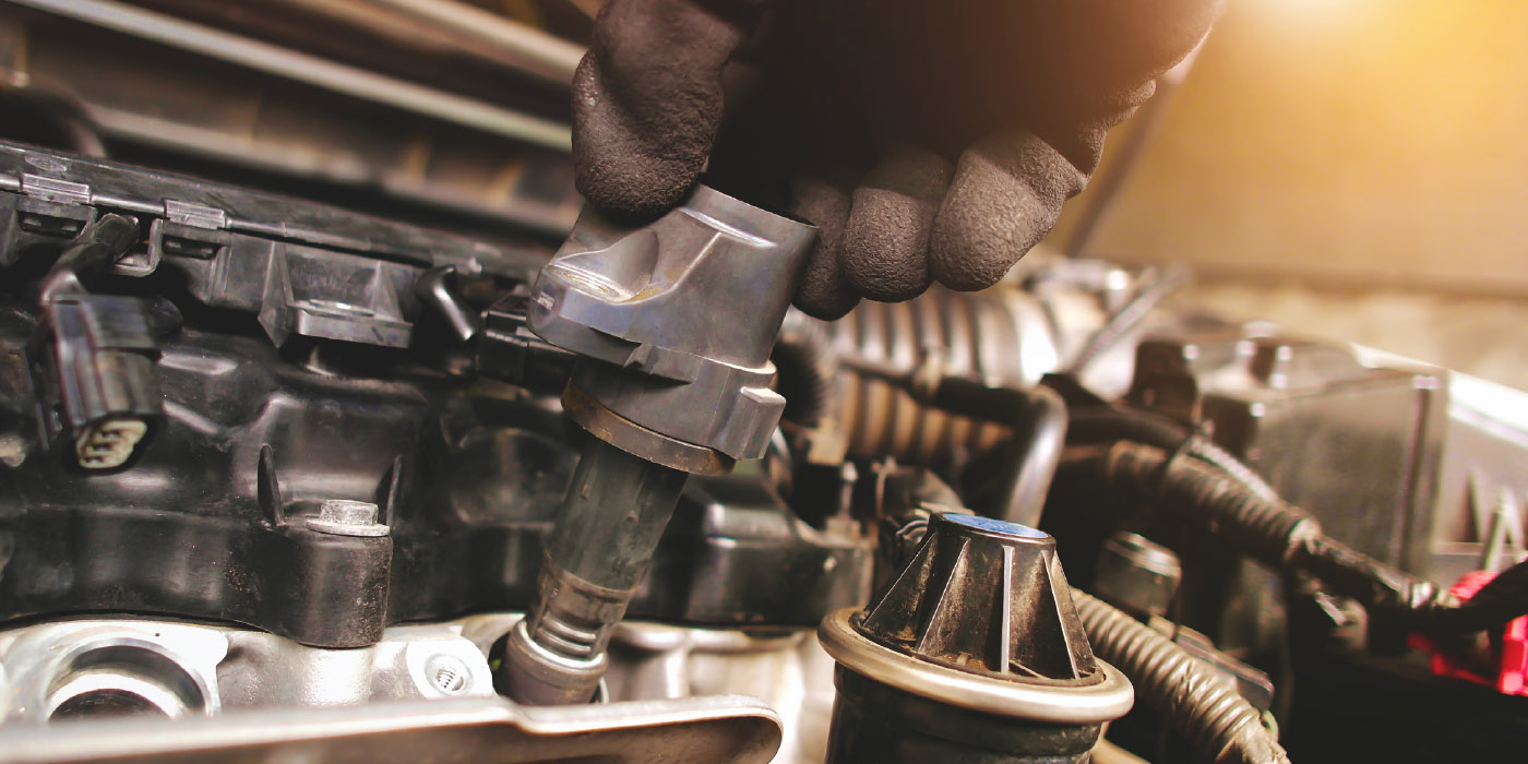
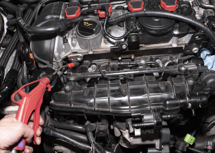
There are several things to be on the lookout for whenever you’re removing the intake manifold. One of the very first steps you should take would be to blow away any dirt or debris from the area with compressed air (Figure 2). This simple step will help to prevent those contaminants from falling into the engine once the manifold is removed. Use special care when disconnecting the wiring harness connectors. Over the years the plastic tends to become brittle, and downright fragile.
You’ll need to remove a number of nearby components before you can remove the intake manifold. The coolant pipe which runs along the front can remain connected, but you’ll need to remove the two Torx screws which secure it to the manifold. The spin-on oil filter will need to be removed, and you should cover the port to prevent any dirt or debris from falling in.
There is an aluminum support bracket which connects the intake manifold to the engine block. This bracket is very difficult to access, but you’ll need to remove it before the manifold can come out. One more thing, the engine wiring harness is routed around this support bracket, so you need to be mindful when working in the area. If you try to leave the bracket attached to the manifold, it will almost certainly stretch or break these wires.
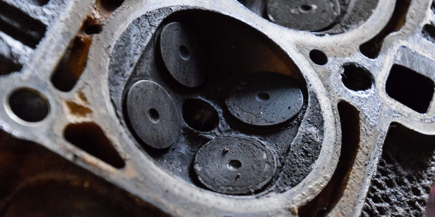
Once the intake manifold is out, you should be looking at two potential add-ons: carbon cleaning, and the water pump. These TSI engines are notorious for carbon buildup on the intake valves, and if you have the ability to clean these deposits it can be an easy add-on sale for your shop.
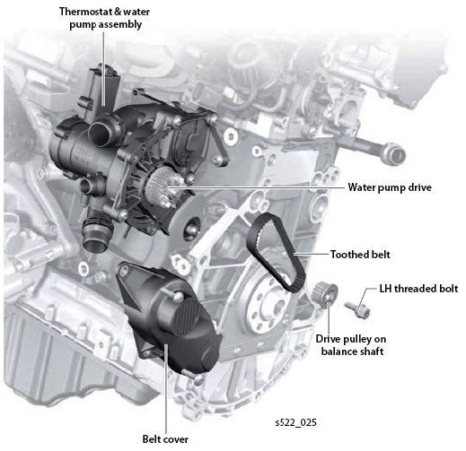
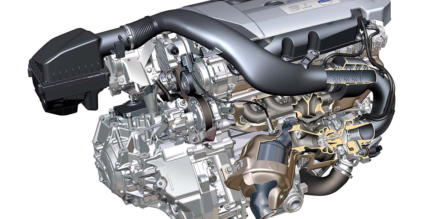
The water pump and thermostat are a modular assembly on these engines (Figure 3). They can be purchased separately, but most of the time they are replaced together. It’s much easier to see these parts once the intake manifold has been removed, so look closely for any signs of coolant leaks in the area.