As driveability technicians, we’ve been taught to solve diagnostic problems by gathering and analyzing data. Data usually comes in three basic forms, the first of which is sensory data that we can see, hear, smell or feel. The second form is measured values gathered by using test equipment like lab scopes and multimeters. The third form comes from computer-generated data displayed on a scan tool.
Unfortunately, analyzing a data stream is a little tricky because what we see doesn’t always represent reality. To illustrate, the injector pulse width displayed on the scan tool is often a calculated, rather than real, value. Differences can and do happen when the pulse width is measured with a multimeter or lab scope. Why do these differences between the data stream and measured values occur? At the most basic level, the answer is that the operating strategy programmed into the engine computer tells the PCM how to react to various operating modes. Unfortunately for the driveability technician, the reactions of the operating strategy to various operating modes may produce data streams that don’t represent reality.
The Multiple Code Ranger
Let’s begin by analyzing multiple codes and data streams on a 1996 4.0L, manual transmission Ford Ranger that came in during the middle of the winter with an illuminated MIL and an electronic transfer case that wouldn’t engage. It also had several “Oh, by the way” complaints that included a rough idle condition and a door chime that would ring intermittently.
The first step in dealing with multiple codes is trying to prioritize the issues. For example, the PCM’s diagnostic memory yielded P1443 (evaporative purge valve fault), P0402 (excess EGR), P1405 (DPFE sensor problem), P0171 (lean B1S1 oxygen sensor), P0174 (lean B2S1 oxygen sensor) and P1838 (transfer case circuit problem) diagnostic trouble codes. Accessing the GEM or body control module yielded codes B1398 (L.F. window circuit) and a B1322 (L.F. door ajar).
Of course, at this point, the customer needs an estimate, so I ignored the P1443 evap code for the moment and moved on to the P1838 DTC concerning the transfer case circuit. This model of Ranger incorporates two relays located in a panel immediately above the throttle pedal that change the transfer case shift motor’s direction of rotation. Substituting the two relays cured the transfer case shifting complaint. Similarly, B1322 DTC was a “no-brainer,” because a failed L.F. door lock sensor is a classic pattern failure that would cause the intermittent ringing door chime complaint.
As for the EGR-related P0402 and P1405 DTCs, a miscalibrated Ford DPFE sensor is again a classic pattern failure that normally doesn’t require extensive diagnosis. In this case, the normal data stream value is 0.5 to 1.0 volts. The current reading of 1.75 volts, which was verified with a DVOM, indicated that the DPFE needed to be replaced.
This left the P0171 and P0174 “lean” codes. On Ford products, the P0171 and P0174 lean codes are also pattern failure codes that usually indicate a dirty MAF sensor, a vacuum leak or a fuel supply problem. A quick inspection revealed a little dirt on the MAF resistors, but nothing conclusive.
At this point, I decided to clear the codes and let the customer drive the Ranger for a few days to see which codes returned. A few days later, a new DTC – P1506 – appeared, which indicates an intermittent high-idle speed condition. In addition, the P0171 and P0174 lean codes had reappeared.
Data Stream Madness
Beginning with the P1506 DTC, KOER testing revealed that idle air control (IAC) valve was operating at a normal 48% “on” duty cycle. The oxygen sensors, on the other hand, were showing very low voltages, which indicated a lean idle condition. The short-term fuel trim was plus 43%, which indicated the PCM was furiously adding fuel to correct the lean idle condition. Seeing that the P1506 and P0171 and P0174 DTCs had appeared together, a vacuum leak seemed to be the likely source of the problem. But a preliminary chec
While I was gazing at the scan tool data stream, the graphing feature showed that the B1S1 and B2S1 O2 voltages had suddenly spiked to about 0.9 volts and that the short-term fuel trim suddenly dropped from plus 43% to 3%. The oxygen sensor voltages then stabilized to approximately 0.5 volts and the SFT to 3%. Revving the engine would bring back the low oxygen sensor voltages and the 43% SFT.
So how could the scan data make the vacuum leak suddenly disappear and reappear? Was I actually seeing a major fuel trim change or was it just false data? Actually, it was both, because Ford’s operating strategy for closed-loop operation is based upon oxygen sensor activity. What I actually saw was the PCM dropping back into open-loop operation after a specified length of time because the lean condition had eliminated the switching activity from the B1 and B2 oxygen sensors. When the PCM drops back to open loop, many of the operating parameters such as idle speed control also revert to fixed, rather than real, values. So, although the data stream was showing 43% IAC, the real-time reading was around 36%. Similarly, although the O2 sensor readings hovered around 0.5 volts, the real-time reading was near zero volts.
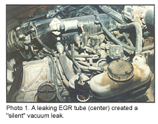 What caused this Diagnostic Dilemma? A major vacuum leak had occurred where the EGR is ported into the intake manifold (see Photo 1). Considering how large the vacuum leak was, my sensory perception might have been flawed because I have a tonal hearing defect. The vacuum leak passed the carb cleaner spray test around the intake manifold and the EGR port, probably because the vacuum leak was so large. In addition, I had used a stethoscope attached to a rubber hose to listen for the leak. Up to that time, this had been a fool-proof method of finding a vacuum leak. Of course, bad hearing or not, using a smoke machine would have instantly revealed the giant vacuum leak. Lesson learned!
The Smokey Bravada
Consider that a ’93 Oldsmobile 4.3L Bravada (same as an S-10 Blazer) shows up in the driveway blowing thick, black smoke out of the exhaust. Again, this is a pattern failure involving a leaking fuel pressure regulator on the 4.3 VIN “W” engines equipped with the CPI fuel injection system. Codes weren’t stored because the duration of the failure hadn’t been long enough for the PCM to analyze the data.
Because the pressure regulator is located inside the intake manifold, the manifold tuning valve must be removed from the top of the intake manifold to expose the regulator. A fuel leak can be easily detected because the inside of the manifold normally has a dirty appearance caused by EGR injection and varnish accumulation. After removing the top plenum section of the intake manifold, it was clear that the leaking regulator had washed the right-hand manifold runner clean. I had three repair options: a new OE unit, a new aftermarket replacement regulator or a reconditioned unit with a new regulator. Considering age and mileage, I recommended the third option. And then the problems began when the Bravada returned several hours later with an intermittent rich complaint!
As for sensory data, the engine performed well other than occasionally emitting an occasional puff of black smoke. Computed scan tool data indicated that the oxygen sensor was switching normally and that the integrator (short-term) and block learn (long-term) fuel trim values were running near 128, which is normal. As for measured values, a fuel pressure test indicated that the system was holding pressure for a long time, especially for a “W” series engine. This seemed to exclude an internal fuel leak. Of course, as you might suspect, this is where the scan tool and measured data made the diagnosis go wrong.
Probably the best solution to any diagnostic dilemma is to get a good night’s sleep. I woke up the next morning realizing that manifold vacuum was causing the internal plumbing to leak when the engine was started. The severity of the leak was determined by heat and pressure. Removing the plenum cover confirmed the diagnosis: a new fuel wash had developed around the inlet and return fuel lines passing through the back of the intake manifold, see Photo 2.
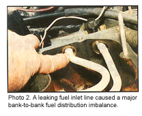 Why hadn’t I originally replaced the fuel line assembly? First, access to the fittings was enormously difficult on this particular application. Second, they weren’t leaking during the initial inspection, so I had assumed (bad word!) that they would continue not to leak as time went on.
Of course, why hadn’t the computed data consisting of oxygen sensor voltage, integrator and block-learn numbers indicated a rich fuel mixture condition? Using its operating strategy, the PCM reduced injector pulse widths to compensate for a rich fuel mixture. That operating strategy made all cylinders run extremely lean, but still failed to compensate for the extra fuel pouring into the left-bank cylinder ports. So the data stream numbers were arrived at by an oxygen sensor averaging the lean and rich cylinder banks, which indicated that fuel trims were normal when, in fact, they were not.
A Single-Tooth Diagnosis
After a friend had recently installed a new 4.0L engine in a ’91 Jeep Cherokee, he found that the fuel injection would immediately drown the spark plugs with fuel. The fuel-fouled spark plugs, of course, immediately created a cranking, no-start condition.
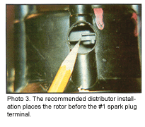
The configuration of Jeep fuel injection systems includes a crankshaft position sensor (CKP) located on the bell housing to indicate TDC position on the #1 cylinder. It also includes a distributor containing a single-shutter Hall sensor or camshaft position sensor (CMP) which, according to published data, synchronizes the fuel injection pulse with the #1 cylinder at TDC on compression stroke.
To summarize, I began by verifying the condition of the CKP at the flywheel and the location of TDC at the harmonic balancer. With that said, I aligned the distributor rotor exactly as illustrated in the shop manual. Okay, the timing should be perfect, but the engine continued to drown itself in fuel. After substituting the MAP sensor and testing the coolant and intake air sensors, I came back to a suspected synchronization issue.
 By cranking the engine with a timing light attached, I discovered that the spark on the #1 cylinder was occurring 120

