Alternator Testing
I’ve also discovered during the past few years that it’s important to initially connect a scan tool to determine the charging system configuration and help analyze charging output. Depending on the diagnostic capability of the scan tool and the software written into the engine control module (ECM), the scan tool might display diagnostic trouble codes (DTCs) indicating problems within the charging system. The scan tool might also reveal intermittent alternator problems by displaying DTCs indicating extremely low or high voltages in the electrical system.
Some charging systems also contain bidirectional controls designed to adjust alternator output. Most scan tools also display an electrical system voltage parameter. Using an accurate voltmeter, compare the scan tool’s voltage parameter with the voltage measured at the battery terminal. If the voltages aren’t within a few tenths of each other, the charging system problem might lie within the ECM or ECM wiring.
The most common cause of intermittent alternator failure is when worn or sticking carbon brushes cause intermittent contact with the rotor slip rings, which is why I never rely on removing an alternator for testing on the part store’s test bench. Testing in-vehicle nearly always provides a definitive diagnosis. Failed alternator diodes, while rare, often reveal themselves as a whining noise in the alternator, accompanied by a loss of charging voltage. Defective alternator diodes can be detected by using alternator test equipment that measures the amount of alternating voltage (commonly known as “ripple”) in the charging circuit.
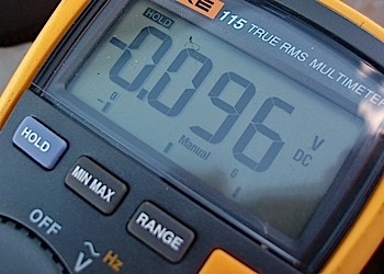
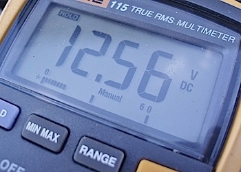
Last, but not least, measure the voltage drop between the alternator and battery by connecting a digital voltmeter in parallel between the alternator (B+) and the battery B+ terminal. (Note: Make sure to do this with the engine running and with a load applied by running exterior lighting and heater blower fan in the “Hi” position.) Using the same method, measure the voltage drop between the alternator case and battery B-, and also measure between battery B- and the body. Voltage drop in all of the above parallel connections shouldn’t exceed Toyota’s specified 0.200 volts. See Photo 3.