It’s interesting to see the look on a technician’s face as a vehicle gets towed into a shop on the back of a truck. That’s the opening scene for a no-start problem. You can usually tell when a technician thinks it’s good, and you can definitely tell when he thinks it’s bad. Not many techs would cringe at the sight of a ’78 Buick on the back of a tow truck because they know they’ll have that puppy turned around in no time flat and be able to do some proper business in the process.
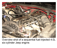
But what about something newer? Perhaps a 1996 Jeep Grand Cherokee with a 4.0L, six-cylinder engine and sequential fuel injection. You may be a little foggy on what it takes to run the new Jeep. The reality is that it is more complex, but it is still straightforward! After all, the spark-ignition/reciprocating-piston engine hasn’t changed much over the last 100 years. What has changed is engine management. It went from mechanical (distributor and carb) to electronic (computer, sensors, injectors and DIS). The rest is basically the same. From the late 1800s to model year 2005, all four-stroke, reciprocating-piston gas engines have the same basic requirements: air (1), fuel (2) and ignition (3) introduced in a properly timed sequence of events (4). Clearly, when our ’96 Jeep came into the shop, it was missing one of these four basics.
 After speaking to the customer (a first-time customer at this garage), it was discovered that the Jeep had an intermittent stumble for three days prior to the full breakdown. The vehicle was not serviced immediately as the customer claimed she was pressed for time, and decided to keep driving the vehicle through the rest of the week with the intent of having it serviced on the weekend. Only the Jeep didn’t want to make it that long.
In most diagnostic cases it is prudent to start out with the basic tests. I like to define “basic tests” as the process of verifying the vehicle’s electrical and mechanical integrity, as well as pulling DTCs and searching for TSBs. When diagnosing a no-start condition on any vehicle, it is vitally important to remember that the engine’s mechanical condition is the primary concern and should be tested first. Beginning with the electronic side of the equation is usually a waste of time as its performance is entirely dependent on the mechanical side of the equation. If a timing chain or belt lets go in an engine, don’t expect to see a cam sensor signal or ignition output. The opposite is not true. Even if the electronics are completely shot, all it takes is a good engine, starter and battery to produce the intake, compression and exhaust cycles. Understanding this one fundamental concept is vital ‹ it can save time, help increase profitability and reduce vehicle comebacks.
If any service bulletins match the DTCs that you’ve retrieved with the scan tool, the diagnosis is usually fairly straightforward. In our case, there were no DTCs. Moving on with the basic tests, we performed the usual checks for battery condition and power, fuel level/pressure/volume, compression tests, general wire-harness and ignition system integrity (usually a visual examination), etc. The ignition wires on this Jeep had seen better days, so we included both a set of spark plugs and wires on our work order to help the Jeep run right once we had the main problem licked. If the same wires and plugs were left in the truck, their eventual demise might come back to us with a customer asking for warranty work. It’s smarter and easier to explain to the customer why a new set of wires and plugs should be installed at this point, along with any other necessary tune-up parts such as filters and hoses.
During the course of the basic testing, the engine was cranked over several times. Compression testing came up within spec. Using an oscilloscope, the functionality of the fuel injector circuits was tested. (Note: Never use a test light, you might destroy the Engine Control Module [ECM]’s transistors/drivers). Noid lights and digital probes can indicate if there is a pulse present, but they can’t show you what the waveform looks like. In other words, they only give you half of the picture. If the pulse is present, the ECM is doing its job. If the waveform is bad, chances are that you have a defective injector. This is why a scope should be used in all electrical component diagnostics. The scope indicated no injector pulse from the ECM. An ignition system check revealed that there was no primary trigger. At this point, we have established three things. By performing our basic mechanical tests, we have determined that the engine is ingesting air and producing a proper level of compression within the cylinders. We also have determined that we have no fuel injection and no spark output. We have only one of the four basic events needed to successfully run the engine. This leaves the last item ‹ a properly timed sequence of events.
At this stage of the diagnostic routine, one usually comes to one of two conclusions that are the source of timed and sequenced events ‹ a bad ECM, or more likely, an improper sensor input. To help further narrow down the problem, we must first perform a brief power and ground test at the ECM. Checking the ignition and battery power inputs to the ECM revealed near-battery voltage, and voltage-drop testing the grounds came up clean as well, with all grounds measuring less than 16 millivolts.
Next was the 5 volt reference, which came in at 5.1 volts. So far, so good. It is usually at this point that some technicians would try to substitute a known-good ECM for the one in the vehicle if they had it available. I caution against this practice, for if there were some electrical problem(s) in the vehicle that caused the original ECM to take a permanent vacation, your known-good unit would be the next to tank. In light of this fact, we hooked up the oscilloscope to the cam and crank sensors. These two sensors are the source for the timing and sequencing of events as performed by the computer. It certainly makes sense to check them for proper operation.
Testing these two sensors for proper operation is what makes or breaks a diagnostic routine’s chances of success. Remember that an ECM can provide a default value for almost all sensor inputs, but it cannot substitute a default value for engine rpm. This is the one signal that absolutely must be present for the ECM to run the engine. If the vehicle has sequential fuel injection, a cam sensor “sync” signal must be present to start the engine as well. There are several important factors to consider when checking cam and crank sensor signals. They are as follows:
1. Determine what type of sensor you are dealing with (magnetic reluctor/inductive sensor, Hall-effect or optical) for the purpose of knowing what type of signal to expect (AC sine wave or DC square wave).
2. Determine the sensor’s required peak-to-peak voltage signal level output.
3. Determine the sensor power supply voltage (5, 8, 10 or 12 volt).
4. Verify the sensor grounds using the voltage-drop test method (sensor grounds must always be less than 50 millivolts, preferably less than 20 millivolts).
5. Determine the proper phase relationship between the crank and the cam sensor.
In order to determine the above, a service manual or other such information source must be consulted. In the case of the 1991 to 2002 Jeep Wrangler, Cherokee and Grand Cherokee 2.5L, four-cylinder engines and 4.0L, six-cylinder engines, the signals and phase relationships are somewhat similar. Let’s take a closer look at why the five signal factors discussed above are so important.
Factor 1 requires determining the type of sensor used for the cam and crank sensors. In the case of the 1991-2002 Jeep 2.5L and 4.0L engines, both the cam and crank sensors are the Hall-effect type. This indicates that the signal we should expect to see is the DC square-wave type.
Factor 2 requires determining the peak-to-peak voltage signal level that the sensor should produce. In this case, it’s a 5 volt peak-to-peak signal for both cam and crank sensors.
Factor 3 requires determining the power supply voltage to the sensor. The wiring schematic for the 1996 Jeep Grand Cherokee shows us that both of these sensors get a 5 volt power supply (the ’91 through ’95 models use an 8 volt power supply input).
Factor 4 requires verifying the sensor ground circuits. This is done to ensure that there is a proper common ground plane between the ECM and the sensors. Since a volt-meter is required to check voltage-drop levels on the ground circuits, it is most convenient to check the power inputs to the sensors (that you researched for Factor 3) at this time as well.
Finally, testing the engine crank and camshaft sensors requires both the information obtained for Factor 5 and an oscilloscope. At this point, we put the “Channel 1” lead of our scope on the crankshaft sensor (ECM pin A8), and the “Channel 2” lead on the camshaft sensor (ECM pin A18), as checking the phase relationship between the two sensors can only be done by viewing both signals at the same time. The scope readings are taken right at the computer harness connector as this verifies the harness wiring and connectors as well as the sensors themselves. With the hookups complete, the spark plugs removed (to lower cranking effort) and the fuel pump and ASD relays removed (to prevent unwanted injection and ignition events from occurring), we can crank the engine over and record the two sensor signal waveforms.
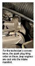 After printing out the waveforms for the two sensors, we were able to compare them with what we had in the service manual spec sheets. Figure 1 is what the factory specifies the signals must look like. The information given here is quite important to the proper running of the engine. Once again, what we’re concerned with here is the proper timing and sequence of events to run the engine. By examining Figure 1, we can see that the crankshaft waveform has three sets of four pulses for each revolution of the crank. The trailing edges of the four pulses within each set of pulses are spaced 20° apart. The first pulse begins 54° after TDC. The second pulse begins at 74° after TDC, the third at 94° and the fourth at 114°. These four pulses comprise the first set of pulses. Each set of four pulses is spaced 120° apart. The first of the second set of four pulses begins at 174°, the second at 194°, etc. Each pulse has a duration of 2° crankshaft rotation. The fact that the three sets of pulses are spaced 120° apart is no coincidence. This number also corresponds to the spacing of the crankshaft throws from cylinder to cylinder within the straight-6 engine. This makes life easier for the engineers who develop the control algorithms and software that is responsible for running the engine. The total number of pulses allows a higher resolution of data input to the ECM that in turn allows greater accuracy of the ignition and injection events. The ECM counts the crank sensor pulses and uses this engine speed measurement to help determine the correct ignition-timing advance, as well as fuel injector pulse-width.
Now for the camshaft sync sensor. The camshaft sensor signal’s leading edge begins at 146° after TDC, and the trailing edge of the signal is at 506° crankshaft revolution. The difference between these two numbers is 360°.
Since the cam spins at half the speed of the crank, we know that the cam sensor Hall switch is shuttered for 180° camshaft revolution. Notice that the sets of four crankshaft pulses for cylinders 3, 6 and 2, are contained evenly between the camshaft signal’s leading and trailing edges (30 crankshaft degrees on either side). This very important detail is called “Indexing.” This is how the ECM determines what order to actuate the injectors, and which coil pack to fire for correct ignition (if equipped with DIS). Without proper indexing (also called synchronization or just “sync”), the ECM would become confused and not be able to start the engine.
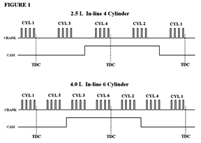 Clearly, the phase relationship between the crank and cam sensors is vital for the ECM to determine and execute a properly timed sequence of events. If the cam signal is “low” (or grounded), the ECM deals with cylinders 4, 1 and 5. If the cam signal is “high” (held at 5 volts) the ECM deals with cylinders 3, 6 and 2. Without a crankshaft or camshaft sensor signal, the vehicle will not start.
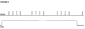
 Figure 2 is a scope printout of the troubled Jeep. Both the crankshaft and camshaft sync signals were missing, or at best, erratic. This was the cause behind the no-start situation. There was no point in disconnecting the sensors from the circuits and testing them independently because we knew that we had our 5 volt reference at the ECM. If the 5 volt circuit was shorted, we would test the sensors separately to see if one of the sensors was shorting the reference line. After installing two new sensors, we had the signal pattern that appears in Figure 3. The behavior of the two sensor profiles is spot-on-the-money. It’s extremely rare for two sensors to take leave at the same time, but it does happen. Using a scope to test signal integrity saves you from the expensive approach of shot-gunning parts. I know that I’m not the only guy to have ever received a defective part right out of the box, so if you swap parts to find a cure without testing, you run the risk of installing a defective part where a good one may have existed.
 Defective parts out of the box are rare too, but not rare enough to gamble extending your work day. Ultimately, by following a specific test sequence with every vehicle that ends up at your shop with driveability problems, you reduce your total diagnostic time spent by increasing efficiency and honing your proficiency. By educating customers on the value of replacing worn or questionable parts, such as the spark plugs and wires at the time of service, your customer benefits by driving a more reliable and smoother-running vehicle. If we keep this up, we just might be able to do some proper business in the process.

