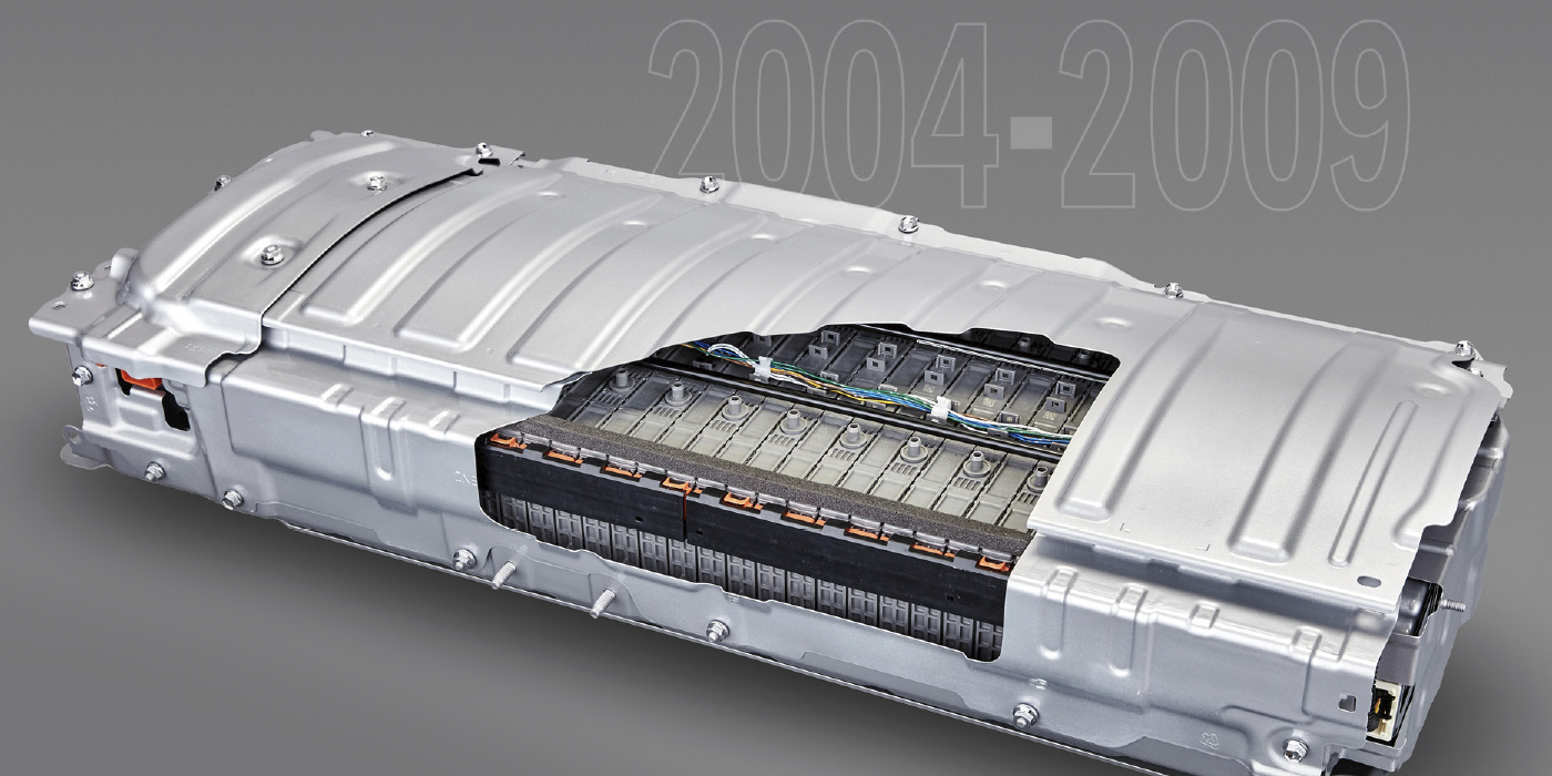
A customer with a 1996 Chevy Tahoe brought the vehicle in, stating that it was shifting erratically, the cruise control would surge from 50 mph to 60 mph and then cut out completely and the speedometer, at times, was drifting. (This Tahoe had a 5.7L vin R engine with a 4L60E transmission coupled to a New Venture 243 electric shift transfer case.)
In order to attempt to re-create the vehicle problems I took the Tahoe for a test drive along with the customer. During this initial test drive, I noticed that at steady cruising speed of about 35 mph, the transmission would suddenly downshift into second gear for about three seconds and then find its way back to fourth gear again. During this test drive, I also attempted to set the cruise control speed at 55 mph. That went fine for about a minute or two and then the engine rapidly surged unannounced to 65 mph, then the cruise control kicked off and the Tahoe began to slow down. The vehicle acted fine except that at between 45 and 55 mph it seemed the worst. I noticed that the speedometer did indeed drift at different speeds. I was lucky to verify the customer’s concern.
After that initial test drive, my instincts led me to believe that the problem could be a vehicle speed sensor (VSS) issue because all of the VSS-related components appeared to be affected. I connected my Tech 2 to the vehicle and didn’t find any stored trouble codes so I recorded a snapshot specifically targeting VSS, output shaft speed (OSS), TP and blank.
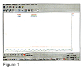 During my troubleshooting I used my handheld GPS to track speed and found that while traveling at a constant 5 mph, the OSS was going from 0 to 8 mph on the screen like a hacksaw blade (see Figure 1). That immediately struck me, and I wanted to verify if the PCM was doing that or if the PCM was seeing that.
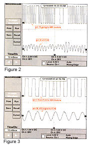
I decided to put the vehicle on a lift to see if I could duplicate the problem in the shop. I pulled out my oscilloscope and grabbed a wiring diagram. On channel 3 of the scope, I inserted the lead into connector C1 pin 15 of the PCM. Pin 15 of the PCM is a DC signal 0-12 volt toggle that is converted from the VSS’s AC signal internally. In addition, pin 15 feeds the ABS module. On channel 1 was connector C1 pin 30 or VSS high AC signal.
I started the truck with the wheels off the ground and put it into drive. The waveform at first starts out looking great. I looked over at the instrument cluster speedometer and it was over 15 mph. I slowed the truck down by lightly applying the brake to achieve about 5 mph because that is where the problem seemed more apparent according to the snapshot and I captured this waveform (Figure 2).
The feed to the ABS module was cutting out, but why? Is it a bad VSS, PCM or wiring? I then looked at the VSS AC signal on channel 1. Look at the AC voltage on channel l carefully. When the converted DC signal cuts out the AC signal stays above 0 volts for about 15 milliseconds! AC voltage is supposed to fluctuate above and below ground. This all was captured at about 8 mph on a lift.
 I stopped the truck and my next step was to check the connector at the VSS. Upon inspection, terminal fitness was great and the wiring was not chaffed anywhere that I could see. I then voltage drop-checked the power and grounds to the PCM. The grounds were at 0.04 volts and the 12-volt leads (including the ones from the ignition switch) were 0.03 volts. At this point I felt the PCM was good.
After seeing the waveform and checking the connections, I replaced the VSS on the transfer case. The VSS took care of the problem. I captured the good waveform shown in Figure 3 after the completed repair. The Tahoe now shifted very smoothly and the speedometer was solid. The cruise control would now set and stay 55 mph without surging. I wondered why this problem that seemed so apparent on a lab scope and even on a scan tool graph didn’t set a P0500 code, VSS output malfunction. I looked up the code and found the enable criteria:
No Manifold Absolute Pressure (MAP) DTCs.
Vehicle speed below 1 mph.
Throttle angle below 3%.
Engine coolant temperature above 60° C.
Engine speed between 1,400 and 4,400 rpm.
MAP below 20 kPa.
All conditions met for 5 seconds.
Amazingly, the PCM has to see 1 mph or less and for 5 seconds to set the P0500! It won’t even set past 3% of throttle angle! Obviously, that enable criteria was not met and for a long enough period of time. Another interesting note is if you go through the diagnostic tree chart for the P0500, GM has you checking the VSS with an AC voltmeter! A voltmeter averages its inputs and would probably never catch the quick dropouts that I had on this Tahoe’s VSS.
Basically, all GM wants you to do is with an AC voltmeter connected directly to the VSS is verify if the voltage varies with rpm. That is an open-ended question in my opinion. What rpm? What voltage should I see? The GM chart would only find a completely dead sensor, not one that is skewed. In my opinion, I would have never found this problem without a wiring diagram and a scope. The snapshot from the Tech 2 did lead me in the right direction, but to solidify the repair a scope is always best. All in all, the diagnosis and repair took a little over one hour. I didn’t think that was bad, it could have been a real diagnostic nightmare!