If you don’t have much experience working with CAN bus communications systems, don’t feel alone. Although CAN bus was introduced by Mercedes-Benz during the early 1990s and adopted by many European manufacturers, many domestic and Asian auto manufacturers waited until the 2004 model year to introduce CAN bus in their lower-end, bread-and-butter vehicles.
Since the fast transmission speeds of CAN bus systems are needed to operate the new air bag, active braking and body control accessories of today’s “connected” vehicles, CAN was required as standard equipment in 2008. While the 2004 and later model-year CAN vehicles have performed reliably during their first 100,000 miles of service, we’re going to see more bus communications problems occur during their second 100,000 miles of service. Since CAN is very application specific and complex, the sole objective of this column is to introduce you to basic CAN bus architecture, terminology and diagnostics.
THE OBDII DLC
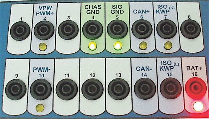
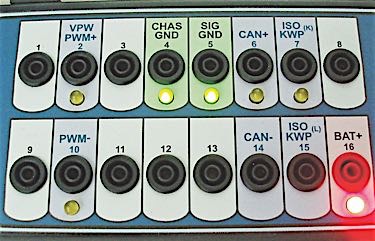
Let’s begin at the 16-pin data link connector (DLC) found under the dash. The DLC pins are arranged in two rows of eight, numbered left to right, with pin #1 located at the top left corner and pin #16 at the bottom right corner. Pin #16 provides a constant B+ power source for your scan tool. Pin #4 normally grounds the scan tool to the chassis, while pin #5 is a common sensor or signal ground. All other pins are application specific, so avoid any testing that might short battery voltage into a bus communications circuit.
If your scan tool isn’t communicating, use a 10-megohm impedance voltmeter grounded to the body to test for B+ at pin #16. If you don’t have B+ at pin #16, use your voltmeter to test both inside and underhood fuses using the vehicle owner’s manual as a guide. If you don’t have a ground at pins #4 or #5, consult a schematic for ground locations. Last, if you’re doing a lot of scan tool diagnosis, it would pay to invest in a DLC breakout box as shown above with LED indicators that show pin #16 voltage, pins #4 and #5 ground function and bus communications activity.
MODULES AND NODES
In general, we refer to large modules as “computers” or as PCMs, ECMs, BCMs, TCMs, etc. A control module is a mini-computer that has a logic and memory function built into it. By “logic” I mean the ability to process data, and by “memory” I mean the ability to store basic information and codes. We might also see the term “node,” which can include your scan tool when it’s connected to the DLC and sending and receiving information via the bus network. Nodes can also be built into switches and other small components. Remember that many electronic aftermarket accessories can create communications compatibility problems when connected to the DLC or bus communications system.
NETWORKING
Since it’s physically impossible to accommodate the large wiring harnesses required by conventional “hard-wired” systems in a modern chassis, engineers now use control modules to perform routine tasks, such as activating interior and exterior lighting.
In modern electrical architecture, the light switch might signal the light control module to turn the exterior headlamps, marker lights and interior lighting on or off. In the same manner, the dimmer switch might signal the light control module to switch from the high-beam to the low-beam headlamp circuit. A control module needs only battery voltage, a good ground and a bus communications system to operate any specific system.
MULTIPLEXING
“Multiplexing” is the method or “topology” of connecting modules in series or parallel configurations. Most early bus systems are referred to as “multiplexed” systems. “Gateway” modules are used to translate the different protocols used in these systems. Terms like “hub,” “master” and “slave” are also used to describe module dominance functions. Since topologies can become quite complex, it’s important to use schematics and service information to understand their relationships within their bus communications circuits.
NETWORKS AND NETWORKING
While terminology varies among manufacturers, a “network” is generally a series of control modules that receives requests and shares information by receiving and transmitting a digital language over one or more bus communication circuits. “Networking” is the process of modules sharing information through different communications protocols or “languages.” Protocols on conventional, non-CAN systems usually switch from zero volts to a specified voltage to create an on/off signal that makes up a communications protocol.
CAN systems differ from earlier multiplexed systems because there are no dominant master/slave relationships among modules. Instead, all modules receive all transmitted messages and each module “decodes” or recovers its own message from a common bus communications network. If a bus system includes a slower protocol, the PCM might, for example, act as a gateway module to translate the two protocols.
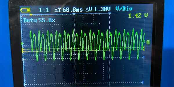
In CAN systems, the signals switch from a floating bias voltage. CAN+ rides on a 2.5-volt bias, which means it toggles from 2.5 bias volts to 3.5 volts. CAN- toggles from the 2.5-volt bias to 1.5 volts. CAN+ and CAN- added together equals a reference voltage of 5.0 volts. When both are displayed on a labscope, a CAN- waveform is the upside-down, mirror image of the CAN+ waveform.
While a labscope can identify the amplitude of a bus signal, the actual waveform varies widely among applications. While CAN+ is usually found on pin #6 and CAN- is found on pin #14, these pins might serve different functions in different vehicles and with different scan tools. Slower protocols, such as UART, might also be included with the CAN system, but are not necessarily connected to the DLC. And, to further confuse the issue, multiple CAN systems are often identified as “CAN A,” “CAN B,” “CAN C,” etc. Remember that the labeling of different CAN systems varies widely among manufacturers, so consult original equipment (OE) service information for application-specific terminology.
POLLING THE MODULES
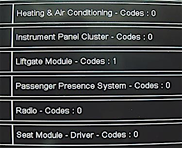
Most OE and aftermarket enhanced scan tools automatically poll or ping the modules or perform a “health check” to confirm that all modules are online (see image). If your scan tool doesn’t automatically communicate with all modules, you must manually poll each module to determine if that module is reporting. If your scan tool indicates “no communication” with a specific module, then you must diagnose the reason for the non-communication.
THE “U” CODE
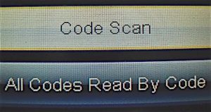
A bus communication failure is indicated when a module stores a “U” code (see image). The last three digits of a “UXXXX” code indicate which module is experiencing communications problems. I’ve found that U-code diagnostics should be approached with caution because a simple problem like a worn ignition switch can set “U” codes by intermittently reducing voltage to the modules. Bad module grounds can also create intermittent problems. Manufacturers are now using much smaller pin connections, which can easily be damaged when probing the connector. In fact, pushed-out pins in the connectors cause many bus failures. In many cases, the OE manufacturer supplies connector-testing kits that eliminate the need for intrusive diagnostic techniques.
CAN TERMINATION
As mentioned above, a CAN– waveform is an upside-down mirror image of a CAN+ waveform. Two 120-ohm resistors, one located at each end of the plus/minus circuits, connect the positive and negative sides of CAN. These resistors are usually embedded in modules. When the CAN network is shut down (ignition off, key removed, no voltage at CAN+ or CAN-), a resistance of 60 ohms should be measured between pins #6 and #14. A 120-ohm measurement would indicate an open in one of the resistors or CAN circuits.