
If your primary workflow consists of pre-2008 models, terms like “Gasoline Direct Fuel Injection (GDI), Homogenous Charge Compression Ignition (HCCI), Variable Compression Ratio (VCR) and Spark-Controlled Compression Ignition (SpCCI)” might sound like engine technologies lurking somewhere in the distant future. But, given that many import repair shops are just beginning to see these engines for advanced driveability diagnostics, your “distant future” might suddenly become your “here and now” when these futuristic engines show up in your service bays.
 On the technical side, these higher-compression engines are able to burn pump gasoline because the burn rate and flame propagation of the injected fuel can be controlled with gasoline direct fuel injection. Running cylinder compression can also be controlled by changing valve timing and valve overlap on variable valve timing (VVT) engines. While both features allow a great deal of flexibility in adjusting air/fuel ratio and running compression to match engine load, both also contribute their share of complexity to the diagnostic process.
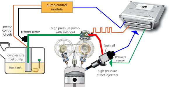
GASOLINE DIRECT INJECTION
The most recent engine designs incorporate gasoline direct fuel injection (GDI) and compression ratios typically ranging from about 11:1 to 15:1. Fuel supply pump pressures are variable and generally range between 40 psi to 75 psi. The high-pressure pump typically produces up to 3,000 psi fuel pressure, in some applications. While you occasionally might see a Schrader valve test port for testing supply pressure, most applications use a low- and a high-pressure sensor to report fuel pressure to your enhanced scan tool via the Powertrain Control Module (ECM).
GDI engines can theoretically operate in eight different combustion modes, ranging from a homogenous air/fuel ratio evenly distributed throughout the cylinder to a stratified charge A/F ratio in which a lean A/F ratio is injected into the cylinder and is followed by a rich A/F ratio injected adjacent to the spark plug. Upon the introduction of spark, the rich A/F ratio ignites the lean A/F ratio to fully oxidize the remaining fuel in the cylinder. GDI systems can create air/fuel ratios ranging from about 13:1 in the “power” mode to over 22:1 in the “lean-burn” mode, which renders the old-school definitions of “rich” and “lean” obsolete.

a lot to learn and VCR is one of them.
VARIABLE COMPRESSION RATIO ENGINES
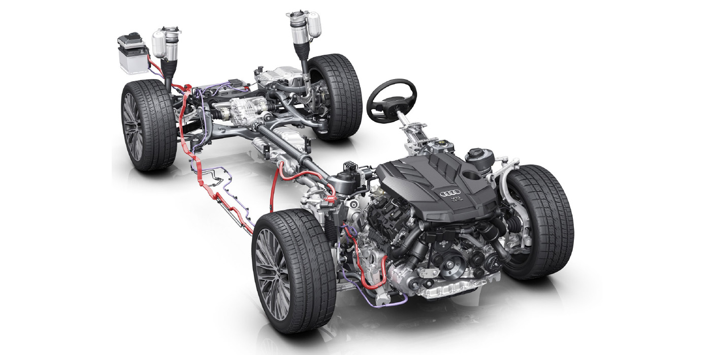
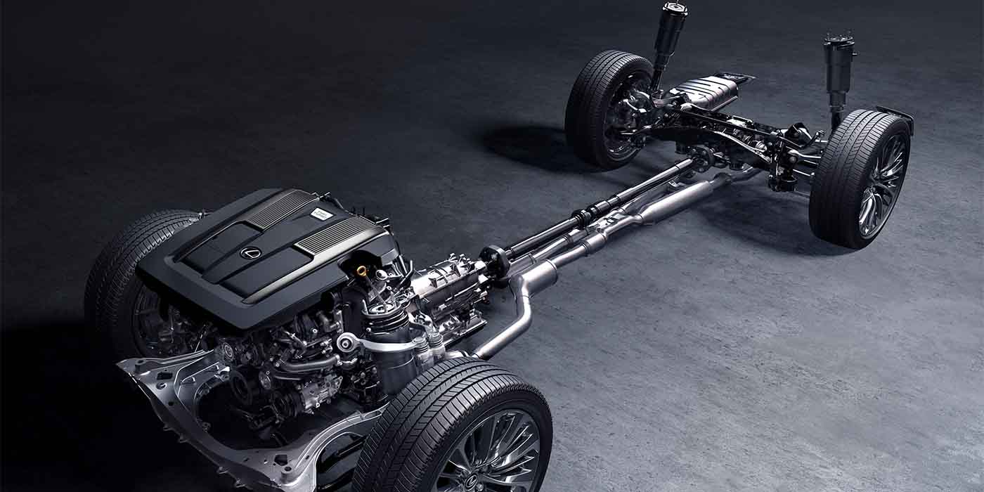
Although the concept of changing compression ratio by changing piston height in the cylinder isn’t new, Nissan is introducing two new Variable Compression Ratio engines in its 2019 Altima models (see Photo 1).
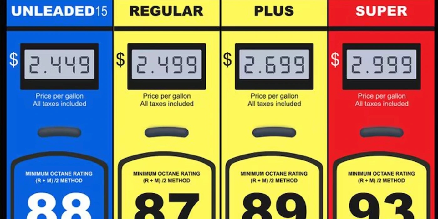
In general, compression ratios vary from about 8:1 for power modes to about 14:1 for fuel economy modes. While these operating strategies sound counterintuitive, wide-open throttle operation fills the cylinder with a very dense intake charge, which increases running compression. Since gasoline octane is limited, the compression ratio must be reduced to 8:1 to prevent detonating the fuel at wide-open throttle. At part throttle, the cylinder is filled with a less dense intake charge, which reduces running compression. For that reason, increasing compression ratio at part throttle will increase fuel economy, which changes our old-school understanding of running compression values.

HOMOGENOUS CHARGE, COMPRESSION IGNITION
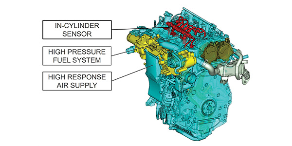
As of this writing, Mazda will introduce a new HCCI engine in its Mazda3 series vehicles in 2019 (see Photo 2). The term “homogenous” indicates that the fuel charge is evenly distributed throughout the cylinder. Once running at operating temperature, the approximately 15:1 compression ratio HCCI engine switches from spark ignition to compression ignition. A compression ignition cycle ignites a very lean air/fuel ratio inside the cylinder, which increases fuel economy and reduces exhaust gas emissions. Whereas old-school engines strive to maintain a stoichiometric 14.7:1 air/fuel ratio, “very lean” has become the standard operating mode for HCCI engines.
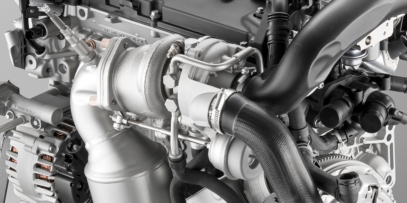
SPARK-CONTROLLED COMPRESSION IGNITION
Introduced by Mazda as the SpCCI engine in 2017, Mazda mates a 15:1 compression ratio with GDI, VVT and a “blower” to produce a spark-ignition engine that actually detonates fuel inside the cylinder (see Photo 3). The striking difference between HCCI and SpCCI is the spark ignition operating continuously on the SpCCI design.
In brief, a lean a/f ratio is injected into the cylinder, followed by a rich a/f ratio directed at the spark plug. The spark plug ignites the rich mixture. As cylinder pressure rises, the lean a/f ratio located around the periphery of the cylinder detonates. Due to the peripheral a/f ratio being very lean, the detonation process is very controlled. Like the HCCI engine, the boundary layer of fuel around the periphery of the cylinder and cylinder head is completely oxidized, which reduces exhaust emissions. Here again, these complex operating parameters have rendered old-school diagnostics obsolete.
SCAN TOOL ISSUES
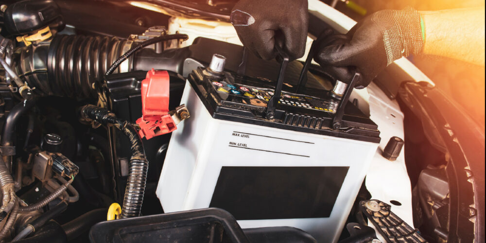
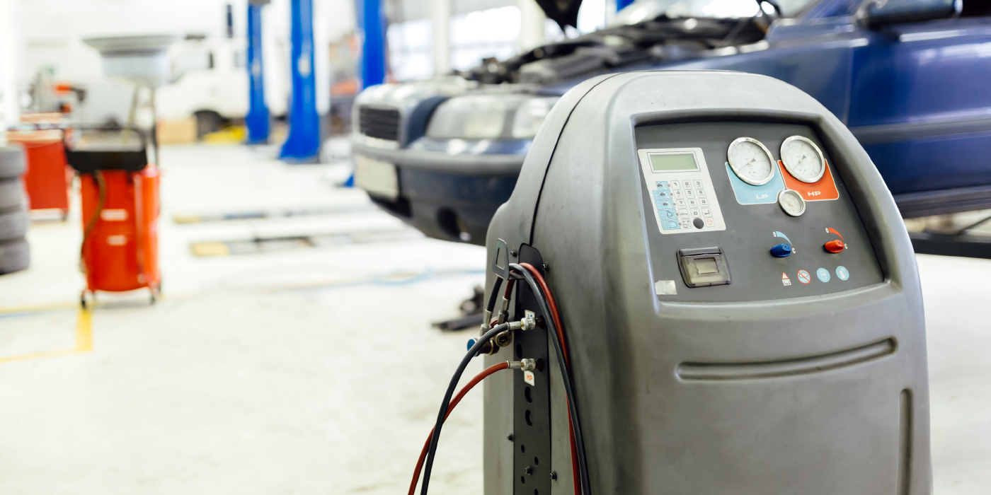
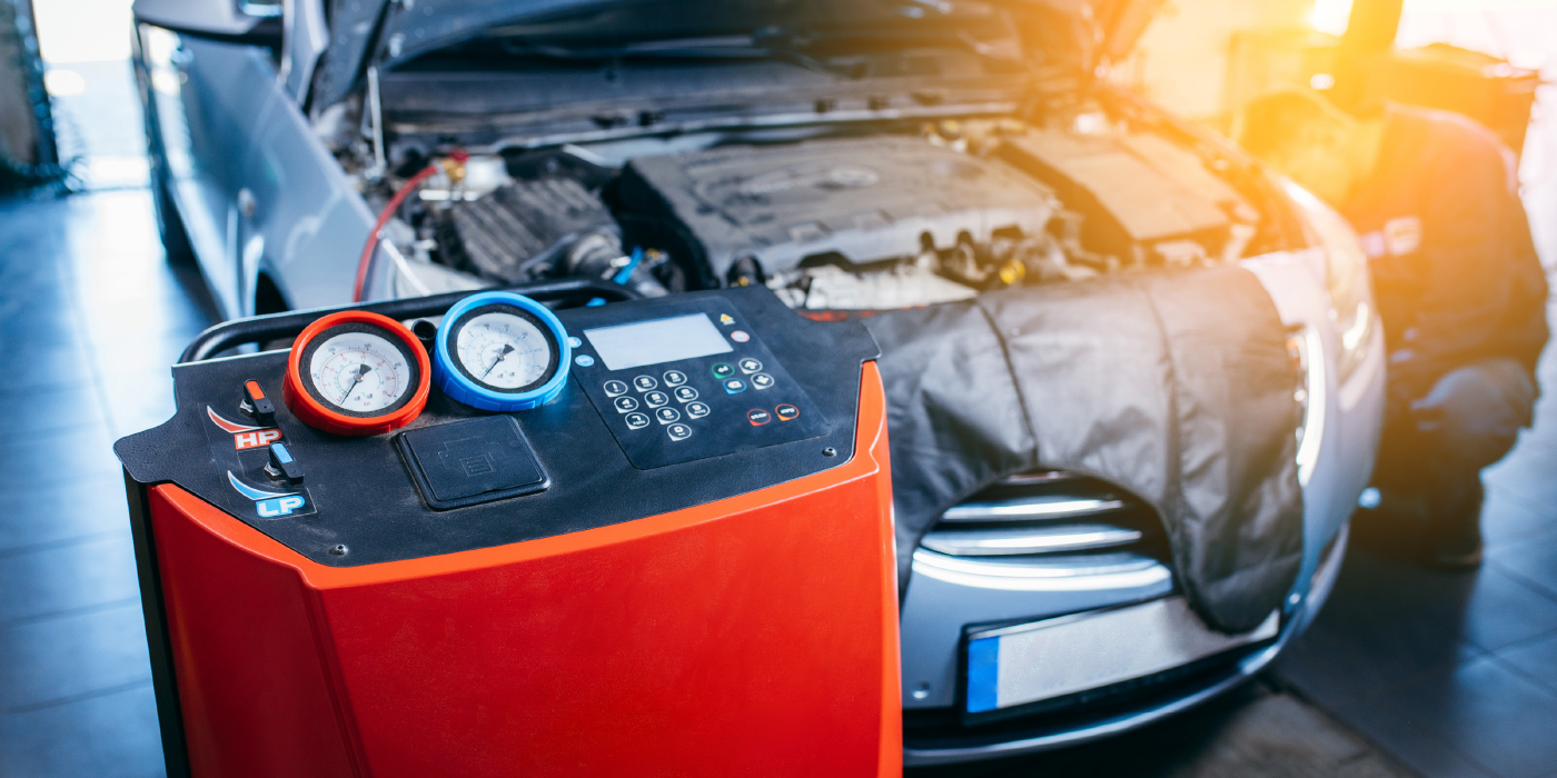
In a nutshell, our Diagnostic Solution has moved from invasive to non-invasive scan tool testing of fuel, ignition, compression and valve timing systems. When dealing with advanced, no-code diagnostics, we’re also very much into using scan tools to compare and interpret numerical data parameters. The more sophisticated diagnostic trouble codes and operating systems become, the more we’re going to be using our enhanced aftermarket or OE scan tool (see Photo 4).
Since enhanced scan tools now contain many different diagnostic menus and windows that deal with different ECM functions, such as ignition, fuel and valve timing system controls, even that diagnostic venue requires good systems knowledge and diagnostic proficiency. But, we still need lab scopes to create waveforms, multimeters to verify voltage, frequency, or resistance, and transducers to verify pressure differentials. These tools won’t be our first choice for solving routine diagnostic problems, but should be considered indispensable members of our “supporting cast” for diagnosing no-code driveability problems.
The ultimate diagnostic question is whether we can better get from point “A” to point “B” by using an enhanced aftermarket scanner or an original equipment (OE) scanner. Keep in mind that OE scanners are usually PC-based and often require expensive access fees or annual subscription fees before they can be used. The better answer is to buy an OE scanner for the nameplates you service most and an aftermarket enhanced scanner for those you service least, especially when your distant future suddenly becomes your here and now.
SIDEBAR
Solving a No-Code Diagnostic Problem with Scan Tool Diagnostics
This month’s Diagnostic Solution depends very much upon the ability of our scan tools to recover and interpret data. Let’s use this composite example to illustrate:
1. Customer complains that the radiator cooling fan runs constantly, but the cooling fan will shut off only if the ignition key is cycled off/on.
2. My client shop recovered a code P0128 from history codes. The engine appears to reach normal operating temperature, at least on warm fall days.
3. But the enabling criteria for P0128 indicates that the coolant temperature didn’t reach the regulated operating temperature of 194º F within a specified time and set of driving conditions.
4. Using an enhanced scan tool, a bi-directional test commanded the radiator fan on/off, which indicates that the ECM has full control of the radiator fan circuit.
5. Will replacing a defective thermostat address the cooling fan complaint? Not likely because we’re dealing with a no-code customer complaint.
6. When told that cycling the ignition switch turned the fan off, I suspected that the continuously running fan issue might actually be a default operating mode initiated by the ECM.
7. Using foundational knowledge, I also suspected that a misreporting engine coolant temperature (ECT) sensor created the no-code fan problem.
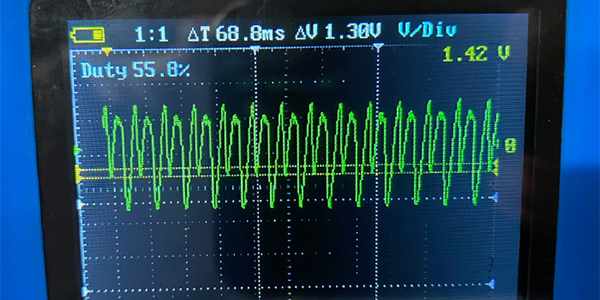
8. During a cold October morning, I used an enhanced scan tool to graph the ECT from about 35º F ambient temperature to the engine’s stabilized operating temperature of about 160º F.
9. After 45 minutes at idle speed with the cabin heater off, real-time temperature measurements never exceeded 160º F. The radiator outlet and return hoses were equally warm with the radiator fan off, which indicated that the thermostat was stuck partially open.
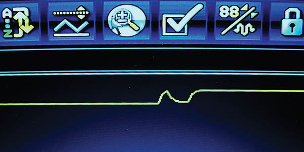
10. Most important, glitches in the ECT voltage graph were likely causing the ECM to believe that it couldn’t accurately measure coolant temperature (see photo 4). I speculated that the ECM went to a default fan-operating mode to keep the engine from overheating.
11. The graph displaying coolant temperature was the conclusive evidence needed to justify the actual repair time of three hours for replacing the thermostat and ECT sensor.
12. Replacing both the ECT sensor and the thermostat solved the mystery of the P0128 DTC and the continuously running radiator cooling fan complaint.