If nothing else, modern master cylinders are notable for their long and relatively trouble-free service lives. The modern master cylinder evolved from the single-piston types popularly introduced in the 1930s to the modern dual-piston, dual braking system cylinders in use today. Master cylinders intended for drum brake use contain one or more residual pressure check valves that maintain a slight pressure in the system. This residual pressure applies tension to the wheel cylinder linkage in the drum brakes and keeps the wheel cylinder piston cups expanded against the cylinder bores. During the 1980s, a quick take-up device was incorporated in some master cylinders to quickly take up the wide brake pad-to-brake rotor clearances existing on some braking systems.
A master cylinder piston is designed to allow the driver to compensate for a low brake pedal by pumping the brake pedal. The master cylinder bore incorporates a “breather” port located behind the piston cup, which allows brake fluid to flow into the cylinder as the brake pedal is depressed. The fluid then flows around the piston seal into the cylinder as the pedal is released.
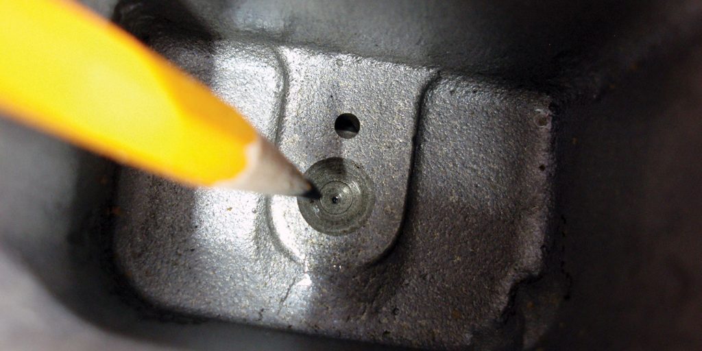
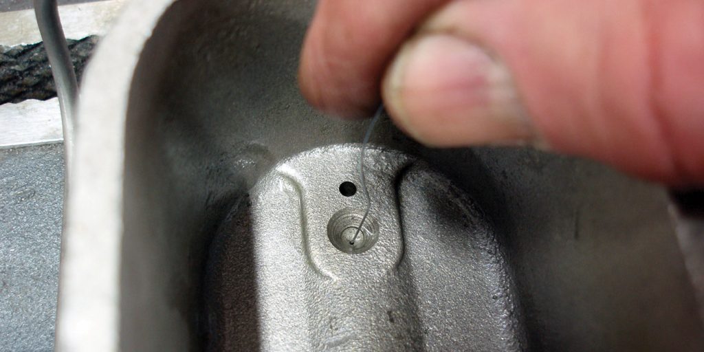
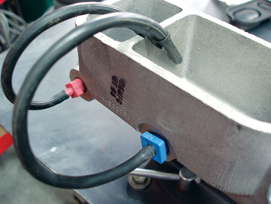
The cylinder also incorporates a “compensation” port (See Photo 1) that is located immediately ahead of the lip of each primary and secondary piston seal or cup. The compensation port is designed to bleed air bubbles from the cylinder bore into the cylinder reservoir (See Photo 2). When the brake pedal is applied, the compensation port is closed as the rubber cup travels past the port. Hydraulic pressure is then developed in the cylinder bore. Operating in tandem, the breather and compensation ports allow the driver to increase hydraulic pressure in the system by pumping the brake pedal.
Dual master cylinders are configured to operate two separate braking systems. The brake booster push rod engages the primary piston first. The secondary piston is normally engaged by hydraulic pressure generated by the primary piston. In a conventional arrangement, the front and rear axles operate as two separate systems. In a dual-diagonal system, the left front/right rear and right front/left rear brakes operate as separate systems. Dual diagonal systems usually provide better stopping power and steering control when hydraulic pressure is lost in one of the two braking systems.
A hydraulic pressure failure-warning switch monitors the primary and secondary systems for loss of hydraulic pressure. If a significant difference in hydraulic pressure develops between the systems, the switch illuminates the red brake warning light on the instrument panel.
A combination brake warning and pressure-limiting valve is usually built into systems incorporating front disc and rear drum brakes. The combination valve is designed to apply the rear brakes slightly before it applies the front brakes. The combination valve also limits hydraulic pressure to the rear drum brakes to prevent rear-wheel lockup during emergency braking conditions. The need for this valve has been reduced on vehicles with anti-lock braking systems because the ABS computer senses wheel lock-up and limits hydraulic pressure to the offending wheels. Unless the combination valve has suffered severe internal corrosion, the valve is normally very reliable.
Although modern master cylinders are reliable, they do require periodic inspection. Most modern cylinders incorporate a semi-transparent fluid reservoir that allows the fluid level to be inspected without exposing the brake fluid to moisture and dirt by removing the sealed filler cap. In addition, many master cylinders incorporate a fluid level warning device in the reservoir that warns the driver of a low fluid level by illuminating a red “brake” warning light. A low fluid level on most anti-lock braking systems will illuminate the red brake and the orange “ABS” warning lights on the instrument cluster.
A low fluid level indicates that the disc brake pads are severely worn or that fluid is leaking from the system. If the reservoir is heavily sludged, the fluid is contaminated with petroleum solvents and/or atmospheric-born moisture. A swollen reservoir cap seal indicates that petroleum-based lubricants or solvents have been introduced in the system. A replacement of all rubber parts or major components in the conventional hydraulic and anti-lock braking systems is usually required to repair this condition.
When diagnosing master cylinders, keep in mind that the master cylinder is but one component of the braking system. In addition, practically all modern ABS systems, no matter how sophisticated, are based upon a conventional hydraulic braking system using a master cylinder, hydraulic brake lines, disc brake calipers and wheel cylinders to force the friction lining against a rotating brake rotor or drum. If the ABS electronics fail, the braking system reverts to conventional operation.
Low or sinking brake pedals and the red “brake” warning light illuminating on the instrument cluster characterize most master cylinder failures. When diagnosing low brake pedals, remember that most manufacturers provide pedal-to-floor height specifications. Low pedal height can be caused by a hydraulic failure in the primary or secondary system or excess clearance developing between the friction lining and disc or drum friction surfaces.
This excess clearance can be caused by a loose wheel bearing on disc brakes or a malfunctioning self-adjusting assembly on drum brakes. The most direct method of locating loose bearings or adjustor linkage is to apply the park brake. If applying the brake increases brake pedal height, the fault lies with the axle actuated by the park brake.
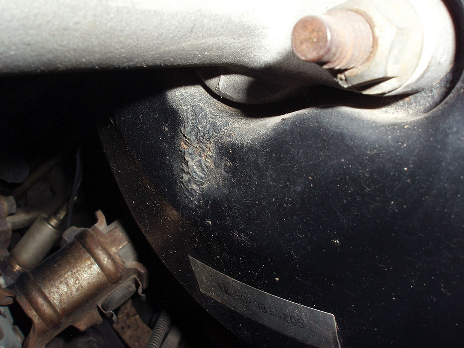
A brake pedal that gradually sinks to the floor when applied indicates that the master cylinder piston seals are leaking internally or that an external leak exists in the system. External leaks are characterized by a low fluid level in the master cylinder reservoir. If an external leak can’t be identified at the brake lines, hoses, calipers or wheel cylinders, the master cylinder might be leaking fluid from its rear piston seal directly into the vacuum brake booster (See Photo 3). The fluid is then drawn from the cylinder into the engine via the vacuum booster hose fastened to the intake manifold.
Internal master cylinder leaks can be caused by pumping the brake pedal to bleed the brakes. In this case, the piston seals are being abraded by pushing them beyond their normal range of travel onto severely corroded portions of the cylinder bore. Internal master cylinder leaks can be pinpointed by removing the brake lines and inserting metal plugs into the master cylinder outlets or onto the metal brake lines connected to the brake hoses.
If the brake pedal continues to sink to the floor, the leakage is in the cylinder itself. Ballooning or other signs of decomposition in rubber brake parts might indicate the presence of petroleum-based solvents in the brake fluid. In this case, the hoses and other rubber parts should be replaced.
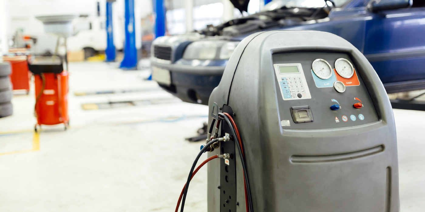
Because some modern ABS systems might require a bi-directional scan tool to bleed the systems, it’s always best to avoid injecting air into the system by bench-bleeding the master cylinder before installation (See Photo 4).
In many cases, the air can be purged by simply tapping on the metal brake lines. In other cases, the air can be purged by collapsing a brake caliper piston a small amount to back-flush a small amount of fluid into the cylinder bore. After the cylinder connections are purged of air, it’s a good policy to flush the entire system using a pressure or vacuum bleeder.