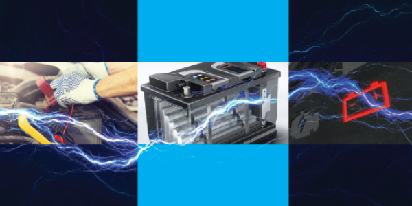
Voltage = Brain Power
Working as a mobile diagnostic technician, I know it’s going to be a long day when I look under the hood and see a greasy-looking battery with thick green scum oozing from around its terminals. The odds are that my client shop has run the battery down trying to start the engine and now it’s literally teetering on the threshold between life and death. I also know that the vehicle’s vital diagnostic trouble codes and freeze frame data might vanish as soon as I connect my scan tool. The ways a bad battery can drive a simple diagnosis off the rails are many, so let’s begin this month’s Diagnostic Solutions by reviewing the foundational aspects of how volts, amps and ohms can affect advanced vehicle diagnostics.
Volts, Amps, Ohms
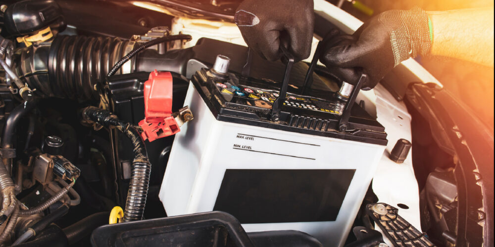
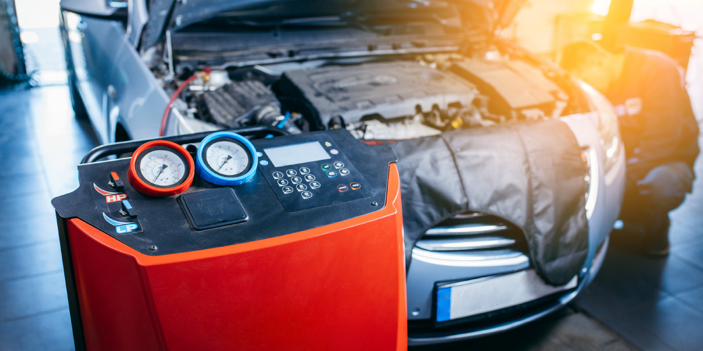
While we’re never going to see perfect numbers, battery terminal voltage is always a good indicator of state-of-charge (SOC) and state of health (SOH). At zero accessory load, a fully charged battery in good SOC and SOH, and with the surface charge removed, will produce 12.6 volts across its terminals (see photo #1) With a normal key-on, engine off (KOEO) accessory load of about 15 amps, terminal voltage on most batteries will quickly drop to about 12.4 volts.
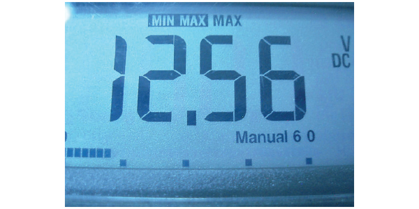
Photo #1: A good battery typically produces a maximum of 12.56 volts before starter engagement.
At 12.4 volts, the battery retains enough amperage to easily crank and start the engine. At 12.0 volts, cranking and starting become a little more problematic because a heavy amperage draw from the starter can erase the diagnostic and the adaptive memories. The loss of adaptive memories represents a rabbit hole that technicians can fall into because a bad battery can cause cold drivability complaints that mysteriously disappear during warm-up and cause automatic transmissions to suffer shift quality problems.
No-Code Complaints
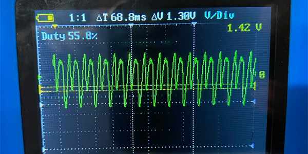
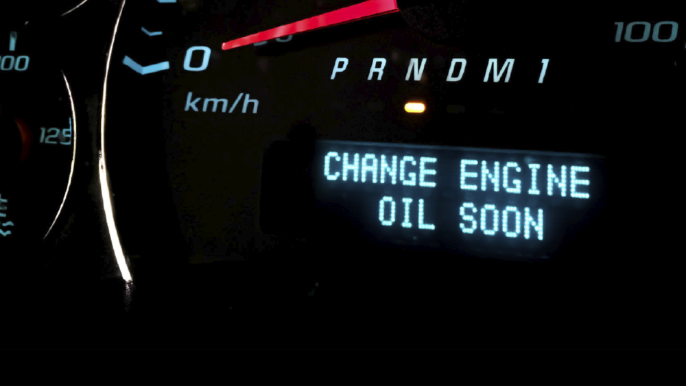
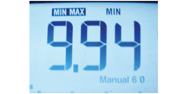
To dig into the subject of battery health a little deeper, let’s say our aging battery also has a bad cell. Each of the six cells generates 2.1 volts, so if we subtract 2.1 volts from our 12.6 -volt total, we have 10.5 no-load volts available at the battery terminals. For our purposes, let’s say the battery’s plate resistance remains constant. So, when the starter motor suddenly draws 150 amps from a battery that is producing only 10.5 volts to begin with, battery terminal voltage plunges well below 9.5 volts, which is the generally accepted threshold for powering the engine control module (ECM) (see photo #2). The end result is an ECM that erases its own codes during cranking, which creates a no-code drivability complaint (see photo #3).

I’ve also seen a badly discharged battery cause the on-board electronics to develop what I call “electronic schizophrenia,” which appears as a series of false trouble codes. An analogous condition might be a human brain suffering from oxygen starvation. We might see, for example, an abundance of U1000-series codes indicating that the vehicle’s modules aren’t communicating with each other. We might also get lucky and find a few modules containing some type of “low-voltage” code. On the downside, we might discover that the engine control and related modules either contain false codes or no codes at all that relate to an intermittent stalling complaint.
Battery Chargers
When testing system electronics, using a battery charger set on “boost” is not a substitute for a fully charged battery in a good state of health. Some battery chargers fluctuate high and low on charging voltage while others generate excessive alternating current in the various on-board sensor and actuator circuits. In any case, attempting to pin-test a circuit while battery voltage is fluctuating high and low is a waste of good diagnostic time. That said, a “clear” charger used for reprogramming will provide the most stable source voltage for extended electronics testing.
Saving The Codes
It’s vitally important to store the codes and important data in the scan tool’s memory while they’re available. After opening the hood or accessing the battery, test battery voltage first. If the battery produces 12.4 to 12.6 volts, it should support the diagnostic memory and scan tool testing. If the battery is hanging in the 10.0-11.0-volt range, it’s best to connect a jumper battery or a “clear” charger designed for reprogramming modules to help offset accessory load. This allows time to retrieve trouble codes, freeze frame data and serial data needed to complete an initial diagnostic analysis.
Analyzing U-Series Codes
A U1000 code indicates that the battery has recently been disconnected and usually indicates that the diagnostic and adaptive memories are now erased. Some vehicles will also store multiple U1000-series codes indicating that the modules weren’t communicating with each other due to low battery voltage.
At this point, a specific U-code might be relevant, providing it can be reproduced. While I’m not fond of erasing codes, I store multiple U-codes in the scan tool memory and then erase the ECM’s diagnostic memory to see if one or more will reappear. If one or more U-codes reappears, we have a hard-code failure of one or more modules or connecting circuits. If the U-codes don’t reappear, they’ve been most likely caused by a low-voltage condition caused by a faulty battery or charging system.
Analyzing P-Series Codes
When we’re looking at approximately 1,700 different vehicle models being introduced to our domestic market each year, it’s tough to arrive at any firm conclusion as to how battery voltage affects the diagnostic memory. Nevertheless, begin diagnosing any P-series code by looking at its enabling or code-setting criteria. Sometimes, battery voltage is a prerequisite condition; other times not. Here again, it’s important to store all P-series code numbers in the scan tool’s memory or, at the very least, jot them on a note pad. As with U-codes, I’ll often erase P-codes to see if they will duplicate at some point during a test drive.
Pending And History Codes
Another aspect of advanced diagnostics is understanding the difference between pending and history codes. A pending code usually requires two consecutive failures (or two “trips) before it will mature into a history code that will illuminate the “check engine (CE)” warning light. That said, pending and history codes are often erased when cranking the engine on a bad battery, which is why we can have a difficult time diagnosing no-code failures caused by two trip codes produced by bad crankshaft position (CKP) sensors and the like.
Pin Testing Precautions
When pin testing any type of electrical circuit, remember that the longer the wire, the greater the loss in voltage from the battery to the end of a loaded circuit. To illustrate, the battery might measure 12.6 volts KOEO. Testing at the ignition switch in a key-on, engine off position, the B+ voltage might measure 12.2 volts due to the length of wiring between battery positive and the ignition switch. Going back to a tail light on an extra-long vehicle, the voltage might dip into the 11-volt range due to the length of the chassis wiring harness. A bad battery will magnify this normal voltage loss to the point that we might believe we have an abnormal resistance in the wiring harness, which we do not.
It’s Time To Change Our Thinking About Battery Testing
1. If the computer is the brain of a modern vehicle, the battery is the heartbeat that pumps life into the arteries of vehicle electronics.
2. Although I’ve seen well-maintained batteries last as long as 12 years, the reliability of a battery rapidly decreases after four years of normal use.
3. A modern reduction gear, permanent-magnet starter doesn’t exhibit the slow-cranking symptoms normally associated with aging batteries.
4. In this day of bar-coded batteries, jotting the installation date on the battery with a paint pen will help you spot an aging battery.
5. Since most modern batteries suddenly fail, I recommend using a conductance tester to evaluate battery condition before attempting a scan tool diagnosis.
6. A conductance tester is the most convenient battery test, especially on discharged batteries.
7. An adjustable carbon pile load tester is the most fool-proof method for detecting sulfated or age-worn batteries, providing that the battery has been recharged to at least 75% of its rated capacity.
8. In most cases, intermittent open-circuit batteries can pass both conductance and load-testing methods. If the battery is suspect, it’s best to replace than to guess.
9. Use a DLC adapter connected to an auxiliary battery to maintain the diagnostic and adaptive memories when the battery is disconnected.
10. A small dual-post battery stored on a battery maintainer serves as a great temporary substitute for a bad battery on a customer vehicle.