SENSOR CALIBRATION
As mentioned above, the ECM requires accurately calibrated intake air and ECT sensors to detect major deviations from the target coolant temperature. Many ECMs perform a simple rationalization test by comparing the indicated intake air and engine coolant sensor temperatures after the engine has cold-soaked overnight. The values should be nearly equal, with the intake air being slightly higher due to normal atmospheric warming.
While we’re at it, many older vehicles hard-wired a separate ECT sensor directly to the instrument cluster temperature gauge. On modern vehicles, the ECT sensor reports directly to the engine control module (ECM). That signal is then transmitted via bus communications to the instrument cluster. On some applications, gauge operation can by verified by using a bi-directional test to “sweep” the cluster gauges.
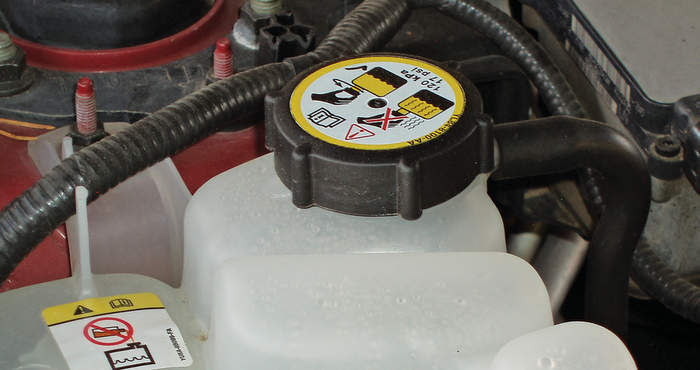
Due to differences between the reflectivity of the target surface and actual coolant temperatures, a minor variation between measured and datastream temperatures might be observed when using a non-contact pyrometer. See Photo 4.
ELECTRICAL FAILURES
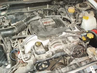
Let’s look at a P0117 and P0118, which indicate, respectively, a low- or high-voltage signal problem within the ECT signal circuit. For our 2008 Subaru Outback with the 2.5L 16-valve “H4” engine, the driveability symptoms include:
1. Hard to start;
2. Improper idling; and
3. Poor driving performance.
I won’t get into the details of the Subaru diagnostic chart for P0117, suffice it to say that the low signal voltage will be caused by:
1. An open circuit;
2. A shorted circuit; or
3. An out-of-calibration ECT sensor.
In contrast to the OE method of testing ground resistance, etc., my preferred method for diagnosing ECT faults is to graph the ECT warm-up voltage on a scan tool. As ECT voltage is graphed, the circuit can be wiggle-tested for broken wires and corroded connections. If the ECT voltage and ECT PID doesn’t correspond to actual engine temperature, the ECT sensor isn’t calibrated correctly. With that said, a typical ECT PID should indicate -40º F when disconnected. If ECT reference voltage is jumpered to the ECT signal wire (which is grounded through the ECM), the ECT PID should typically indicate approximately +300º F.
Moving on through ECT circuit diagnostics, our Subaru’s ECM is looking for a “target” signal of at least 0.2647 volts. The ECT monitor requires 500 milliseconds to detect the failure and the malfunction indicator light (MIL) illuminates shortly thereafter. Since 40 idling cycles are required to automatically clear the P0117 DTC, it pays to look at history codes for evidence of ECT electrical malfunctions.
Most important, let’s look at what happens during a P0117/118 circuit failure. With our Subaru, the ECM goes into a fail-safe mode that fixes ECT at a default value of 158º F. According to service information, the idle speed will correspond to the default temperature value and the idle speed control (ISC) will not perform a re-learn. The air conditioner will not turn on and the engine cooling fans will default to high-speed output. The variable valve timing will also default to 0% duty cycle.
While the P0128, P0117 and P0118 DTCs are indicative of many common cooling system problems, they also indicate how engine operating systems can be affected by incorrectly calibrated thermostats. In any case, when pursuing intermittent or random driveability and stalling complaints, it’s wise to check for cooling system-related DTCs and to pursue a basic cooling system diagnosis before jumping to any diagnostic conclusions.