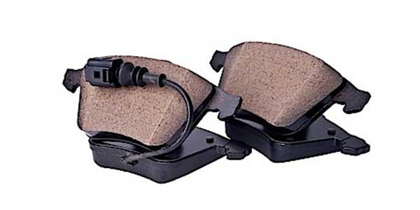
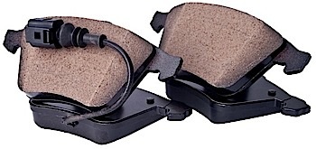
Electronic brake pad wear sensors can be found on a variety of vehicles, including domestic, European and Asian cars and trucks. These give a more accurate reading on brake pad depth compared to squealer metal tabs that make noise that most drivers manage to ignore assuming it will go away over time.
Brake pad wear sensors have been around for more than 40 years. But in the past decade, they have evolved so that brake wear can be estimated. This has allowed the driver to pick the right time to have their brake pads replaced.
Basic Systems
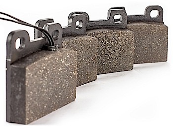
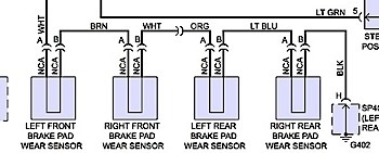
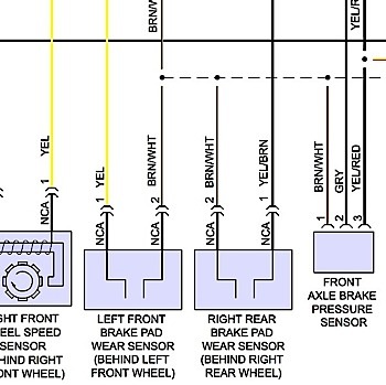
Most basic brake pad wear systems have a sensor at each corner of the vehicle on the inboard pad. These systems can vary in the number of wheels that have sensors and where the placement is on the pads. Since the 1970s, these systems have consisted of just a loop of wire with a small amount of current running through it.
On older systems, the sensor had a known resistance value. When the resistance exceeded 2,000 ohms, a rectifier circuit in the instrument cluster sensed it as an open circuit and turned on the light. The most common failure for these circuits is physical damage and corrosion at the connector.
Some systems connect the sensors in series. The system is not able to tell what brake pad is worn past its limits when the circuit loop is broken. This can make diagnosing an open circuit difficult. You will have to test for continuity at the connectors to isolate a problem.
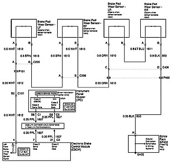
Some systems might just have one sensor per axle. The logic being that brake pads should wear evenly on both sides. Later systems connect the sensor loop to a module that will activate the warning light in the instrument cluster.
Modern Systems
Modern brake pad wear sensors can do more than just warn the driver of a worn brake pad. These new wear sensors work with the rest of the brake system and can estimate the mileage until the brake pads wear out.
New wear sensors have two resistor circuits in parallel at two depths. The first resistor circuit is set at a higher position in the sensor, and the second resistor circuit is at a lower position.
These are more than just wires that break when the last 3 mm to 5 mm of pad material makes contact with the rotor. These sensors can warn the driver and technician of the state of the brake pads long before it becomes a safety problem.
When the first resistive circuit is broken, the resistance in the sensor will increase due to the resistors having a parallel structure. When the second wire is broken, the circuit is now open.
The first resistive circuit will not typically set a off warning light. The information is used by the brake system to estimate the pad life remaining using other information. Known as two-stage wear sensors, these are monitored by the ABS module and instrument cluster module on some vehicles.
The system wear sensors use information such as wheel speed, mileage, brake pressure, brake disc temperature and brake operating time to determine the life remaining in the pads. This is displayed in the information center or with a warning lamp that may go from yellow to red. Some systems may show the life left on the pads during start up.
The old trick of splicing the wires together to bypass the warning light will not work with two-stage sensors. The module passes voltage through the circuit and uses the amount of voltage drop to confirm the sensor is working. If the system notices that no voltage is dropping across the circuit, it will set a malfunction warning light.
Parking Brake Calibration
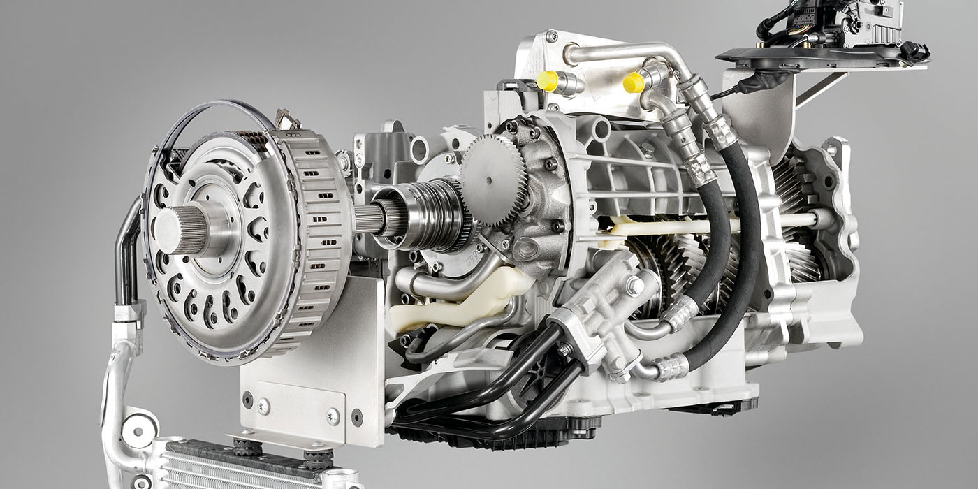
On some European vehicles like Mercedes-Benz models, rear pad life is measured using the electronic parking brake module. The system engages the rear brakes with the stepper motor in the caliper or the motor that actuates the cables. The system will count the number of motor rotations needed to engage the rear brake pads. Some systems do this measurement with the key off.
Service Precautions
It is always a good idea to replace removable wear sensors. Over time, the heat from the brakes can damage the wiring and clip that holds in the sensor. These sensors are inexpensive when compared to a comeback. Many premium pads will include them as part of the brake pad set. Also, these sensors are available from many aftermarket suppliers.
Never forget to reset the brake life service indictor. On some vehicles, this can be done using just the driver information center. On other vehicles, it might require the use of a scan tool.