Why Real Twin Turbos Aren’t Seen on Diesel Engines
A noticeable trend in OEM vehicles, and the aftermarket that supports them, is a lack of twin-turbo systems. However, when it comes to performance spark-ignition engines, twin-turbo set ups appear to be fairly common, while in turbo diesels it is only seen on very strict OEM conditions and rarely in performance diesel conditions.
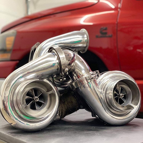
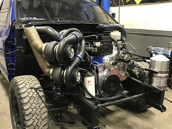
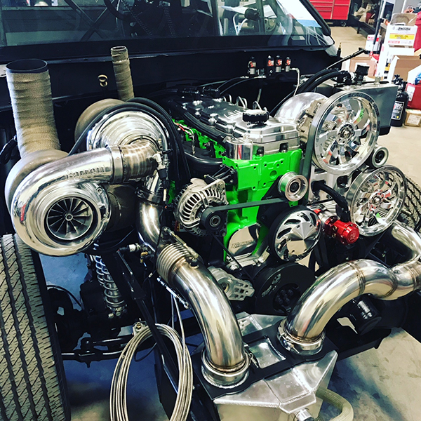
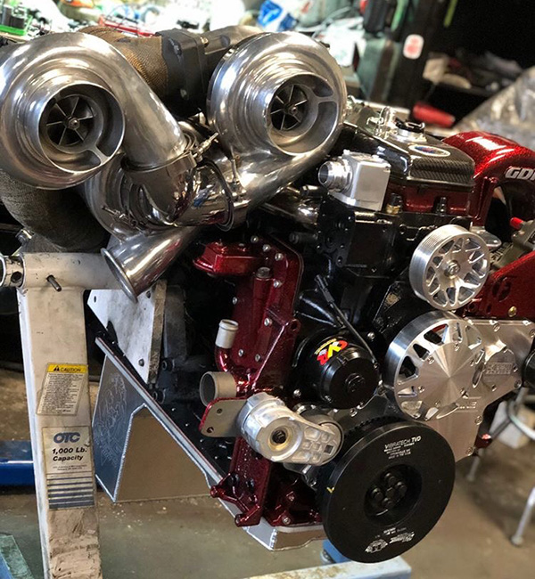
To clarify, I am talking about ‘real’ twin turbos, in the same way we see twin turbos on spark ignition engines. I am not talking about compound turbocharging, which, in the diesel world, is often called twin turbocharging. I want to define twin turbos as two turbochargers of equal specifications being driven by one half of the engine’s displacement while feeding a common plenum.
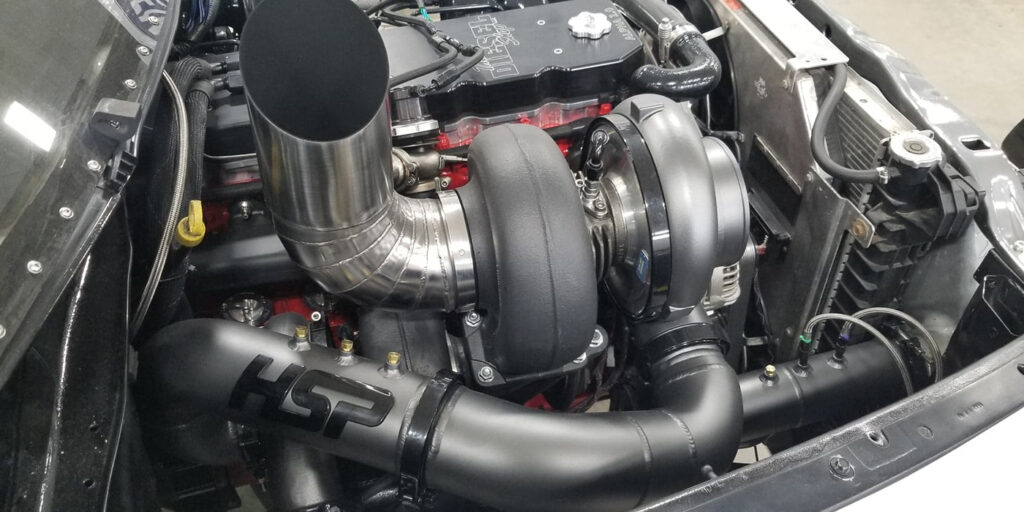
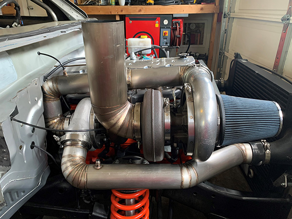
Compound turbos will be defined as a single manifold driven turbocharger that then feeds its exhaust gas to a larger atmospheric turbocharger. That atmospheric turbo intakes from atmosphere, feeding the cold side to the compressor inlet of the manifold turbo, which will add additional compression to the new, higher-pressure atmospheric condition being created by the atmospheric turbocharger. This definition of compound turbocharging may sound complicated, but it is very straight forward.
If you’ve ever seen a compound-turbo setup, you can clearly see it is not a twin-turbo setup. Why do diesels utilize compounds over twin turbochargers? We first need to move back to the basics of engine design and engine airflow consumption rates. When looking at diesel engines they tend to not spin high rpms. I have not seen to date a light-duty truck engine that comes with a red-line above 5,000 rpm. To add to that, the average performance turbo diesels also do not operate above 4,000 rpm. This means that even with a decent cubic inch engine, a diesel motor will require a fair amount of air density multiplication to create an airflow consumption rate to reach the appropriate air fuel ratio (AFR) to produce wheel horsepower.
The basis of forced induction is that it is an air density multiplication, in which we are only multiplying the air the motor is asking for in its N/A trim. A good example is the 5.9L Cummins engine versus a 6.0L LS. In this example we will use the same volumetric efficiency (VE) to demonstrate the rpm difference between the two engine sizes with different cfm N/A. Trying to make 500 whp @ 3,000 rpm with a 5.9L Cummins engine is vastly different than 500 whp @ 7,000 rpm with the 6.0L LS.
A 5.9L Cummins @ 3,000 rpm and 80% VE is drawing in N/A 249.31 cfm. The 6.0L LS @ 7,000 rpm and 80% VE is asking for 593.29 cfm. Both engines are operating at 20% less than what the motor is asking for due to valve timing and port speed issues.
Once we know what an engine is consuming when N/A, we need to start calculating the amount of boost pressure it will take to reach 500 whp. One thing to note about forced induction is that it multiplies the N/A cfm by the density ratio (DR).
For demonstration purposes, both motors are drawing in 100°F air. The air weighs 0.0709 lbs. per cubic foot. A diesel engine averages 8 whp per 1-lb. of air consumed. With this we can take 500 whp and divide by 8, giving us 62.5 lbs./minute. Next, we divide by the weight of the air per cubic foot 62.5÷0.0709=881.52 cfm. That is what we need to consume at a lower AFR to produce 500 whp in the turbo diesel engine regardless of the turbo diesel motor selected. Next, we take the number and divide it by the engine’s N/A cfm. In this example it will be: 881.52÷249.31 cfm giving us a DR of 3.535.
Next, we calculate the target DR of the 6.0L spark ignition engine to produce 500 whp @ 7,000 rpm with the engine at 80% VE. It appears somewhat consistent that spark ignition, on gasoline-based fuels, makes 10 whp per 1-lb. of air, so that will give us 50 lbs. air/minute. Again, we divide by the weight of the air per cubic foot: 50lbs÷0.0709=705.218 cfm. To find the DR target we divide that number by the N/A cfm: 705.218÷593.29=1.18 DR.
With air temperatures at 100°F, we can start to see how the lower rpm and slightly lower displacement diesel is going to need a much higher boost pressure for it to reach the target DR.
To calculate the boost pressure required to reach each system’s target DR, we need to do some additional turbo math. With the DR calculated we can use that to find the pressure ratio (PR) needed to hit that density ratio in a much shorter amount of time. For a spark ignition engine at a 1.18 DR it is probably going to require 1.2-1.5 PR. Using 1.2 x atmospheric pressure (we are using 14.7 psi or sea level), then subtract atmosphere (14.7) = 2.94 gauge psi (psig). A 1.5 PR equates to 7.35 psig.
At these pressure ratios, the turbochargers are not working very hard. Most turbochargers can support these low pressures even when working at high rotor speeds for a length of time that matches with the manufacturers target life span. The aftermarket performance crowd will not need a high amount of exhaust energy sustained to maintain the lower boost pressure, making for a durable, long lasting, and when sized accordingly, responsive turbocharger.
The low rpm diesel that has to run a higher DR will also be running a higher PR. With higher boost pressure comes the introduction of increased compressor outlet temperatures, which in turn, can push the PR needed even higher to counter the loss in DR. There is a high probability that, on the diesel engine, a PR of 3.7 to 4.0 will be needed to reach the target DR. This comes out to 39.69-44.1 psig. Now we start to see why true twins aren’t common.
Running twin turbos on this application presents the issue of getting two smaller turbochargers to sustain 36-44 psi each, while feeding into a common plenum by 3,000 rpm. Diesel exhaust has low energy due to the efficiency of the combustion event and fuel type. We could look at two turbos with a combined flow rate of 62.5lbs./min, but now the turbos are becoming undersized when it comes to their bearing system. This causes high fatigue cycling and failure rates in these smaller turbos when pushing them to high boost pressures that they were never intended for. The shaft speeds get extreme, fatigue cycling goes up, and we still have to feed the turbos enough energy to maintain this pressure when we could’ve run one single, appropriately sized turbo with a more robust bearing system in place, along with less shaft speed on the rotor assembly. The turbo will spool similarly, because in twins each turbo believes it is being fed by one half engine displacement, so torque per rpm with a properly selected turbocharger will remain similar.
What we would probably find is that a single turbine with more surface area will run a higher engine VE number than the two small turbine wheels in the twins. This is something that I have noticed when looking at total boost versus turbine wheel size versus engine VE on turbo diesels.
I can conclude with some real world uses of diesel engines running parallel turbos, but it should be looked at carefully as to how and when they are used. The QSK 95L Cummins motor uses four 125 lbs./min. turbochargers at 36-44 psi to produce the power it does while maintaining the proper combined flow rate needed. The turbos are extremely large for reliability at high boost pressures. If the turbos were smaller, there is a good chance that Cummins would increase the displacement of the engine to lower the target operating boost pressure.
Looking at Pro Mod Duramax motors, they have smaller turbos for the twin-turbo setup, but every single one is also nitrous assisted. They use the nitrous-oxide to spool the turbos on the line, as well as for supplementing the oxygen content throughout the run until they are down the track. When they have issues with the nitrous systems, the engines usually fail to spool the true twin turbos, and if they do, the 60’ and E.T. is far higher than what it would be on nitrous.
The nitrous-oxide troubles could be alleviated through the use of compound turbocharging, but this could add more weight, package constraints in the vehicle, or just be seen as not cool/different. I love all the different ideas in the diesel industry, and I’m always excited to see what folks come up with next, but ‘real’ twin turbos are unlikely.
This article is courtesy of Engine Builder.