 Having to remove valve or front cover of an engine to check engine timing marks can rarely be completed in under an hour on most modern engines. But, capturing the waveforms from the camshaft and crankshaft sensors can be completed in under 30 minutes. This diagnostic approach can also diagnose circuit and sensor problems.
WHEN
Anytime there is a code related to the synchronization of the camshaft and crankshaft and sensor/circuit malfunction codes, the waveforms should be captured for analysis.
WHY
Using a scope to capture the waveform of engine position sensor can give insights into three things about the engine. First, measuring the sensor output gives you insights into the health of a sensor and the signal. Second, the waveform can reveal if the tone ring is damaged. Third, when multiple sensor waveforms are measured at the same time, it can show the engine timing.
WHAT IS NEED
1. Oscilloscope/Scope: You need a scope that can capture and store a waveform. The more channels, the better. A four-channel scope can be faster just because you can look at four sensors on one screen. Also, if you are measuring inductive crankshaft sensors, you can run out of channels very quickly without four channels.
2. Access to “Known Good” Waveforms: You can capture the clearest waveform with a scope, but if you don’t have a “known good” waveform for comparison, it can be difficult to make a final diagnosis.
Engine position waveforms can be found in the service information for some OEMs. It is even rarer to find waveforms with multiple channels in OE service information. Some scope manufacturers have developed databases of “known good” waveforms. The size of databases should weigh heavily on your next scope purchase. Other sources are communities of technicians that share waveforms. These communities have been around for decades and some shop management and service information products are also building databases.
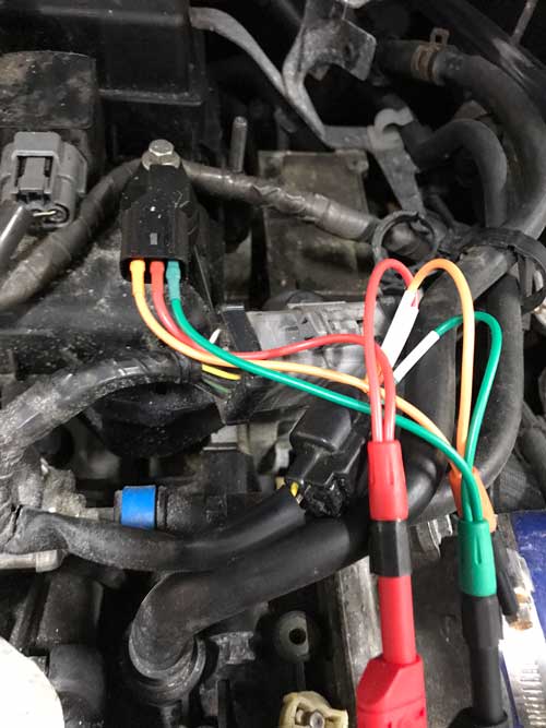
3. Probes: There are a few ways to connect to engine position sensors.
• Breakout Harness: This type of harness can be installed between the connectors. This is the least invasive and will not damage the connector or harness.
• Backprobing: If you can access the back of the connector, you can use a pin probe to attach the back of the connector. Don’t push a pin in too far.
• Piercing Probes: If you can’t access a sensor’s connector because it is located deep in the engine, you can use a piercing probe. But, always repair the insulation.
SCOPE SETUP
Triggers: No triggers should set.
Voltage: Most crankshaft and camshaft sensors use a five-volt signal, so a ±10 volt axis works. A few sensors use a 12-volt signal. A ±20 volt axis will work on these.
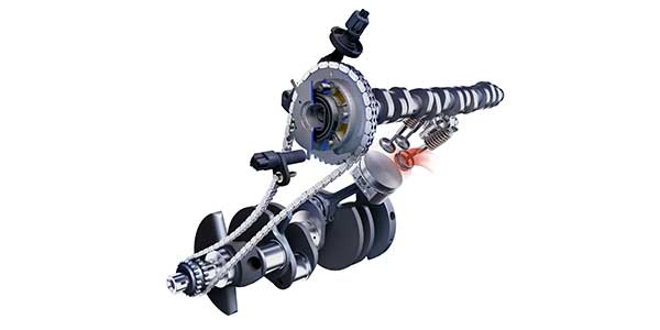
Time: The crankshaft has to turn twice to get one revolution of the camshaft. This means that 720 degrees of crank rotation equal 360 degrees camshaft rotation. You will need at least three revolutions of the crankshaft to compare the relationship to the camshaft(s). Adjust your time scale to capture at least three turns of the crankshaft on a screen.
Like wheel speed sensors, engine position sensors can be passive (floating) or active. In the case of engine position sensors, inductive (floating) or hall effect.
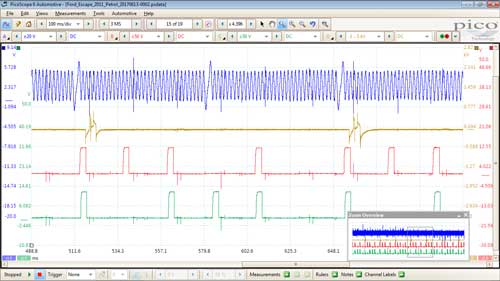
Inductive sensor setups typically have two signals. One will be a positive voltage, and the other will be a negative voltage. They should be a mirror image of each other.
RUNNING THE TEST
Once you get your scope connected, you can run the test either cranking or at idle. Revving the engine will not improve the waveform.
Let the engine run and fill the buffer of the scope. In some cases, you will need to deactivate the variable valve timing by either disconnecting the actuator or solenoid. Another method is using a scan tool with bi-directional code.
ANALYZING THE WAVEFORM
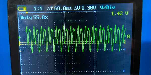
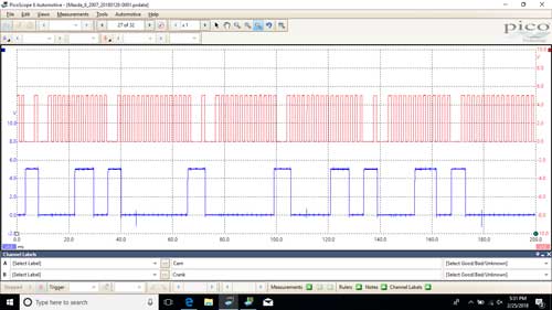
Depending on the scope you own, you should have between 24 and 32 frames of the waveform. You are looking for a screen that has three or four revolutions of the crankshaft.
Most crankshaft signals will have an area of the ring where the teeth are spaced out or are a different size. It is impossible to say if these indicate top dead center or another event. But these can help you spot 720 degrees of crankshaft rotation. During this time, you will see one rotation of a camshaft.
Hall-effect and inductive sensor waveforms should be clean and the corners or peaks should be sharp. A clean power signal and ground are essential for a hall-effect sensor to operate. If the power going in has a lot of “hash” or interference, the signal coming out will have also have the hash.
If there is resistance in the sensor’s circuit or connector, the signal will change in height/voltage on the screen. The smallest amount of corrosion can have a huge impact on the signal, and if the ECM can read it. If the signal’s peak drops below a specific value, like three volts, it will set a code.
When comparing the waveforms, your known good waveform might come from a different scope and settings. The peaks could appear to be wider or skinner, but the patterns should match. If the base engine timing is off, the patterns will not line up.
FAILURE MODES
By checking engine timing with a scope, you can see if the timing chain has stretched or a chain has jumped timing. This will confirm if the camshaft and crankshaft correlation codes are real or if there is an issue with the sensor.
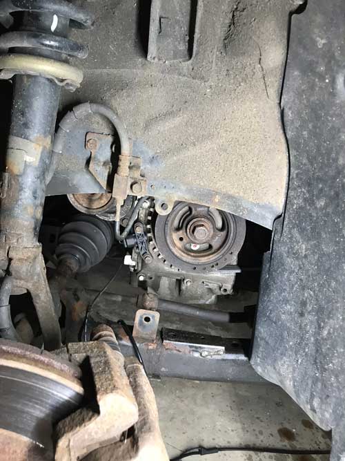
With some crank position sensors on the front of the engine, the bracket that holds the sensor can be bent and change the air gap between the sensor and ring. Also, if the ring on the crankshaft is on the front of the engine, it can be damaged by debris that can crack or knock off teeth. This can easily be seen in the waveform.
If you are dealing with a replacement engine that is either salvaged or remanufactured, it is possible that the wrong ring is on the camshaft or crankshaft. This could be due to a mid-year change in the engine’s sensors. Often, a salvage yard will try to sell an engine that is similar, but not the same year.