Volkwagen has been selling diesel-powered cars in the U.S. for almost 30 years. Turbocharged versions have been available for 25. That is a lot of experience and a testament to the development of a reliable, efficient and durable powerplant. The introduction and development of the TDI (turbocharged direct injection) brought the VW diesel into the new century with a big head start on any competition. With the exception of Mercedes-Benz, VW has been the only manufacturer to sell diesel passenger cars in this country in any great numbers.
Diesel power may not be for everyone, but I would guess that many people would not even realize that a TDI was diesel powered unless they were told. Compared to the diesel-powered cars of 20 years ago, the TDI is quiet, powerful and smooth. Economy of operation runs the gamut from the high fuel mileage, to the lack of needed tuneups.
Since there are no longer any adjustments to be made for valve clearance, timing or cold weather operation, maintenance is limited to oil changes and filter replacement. Even extended-mileage timing belts are now available that can extend the period between replacement. Depending on climate conditions and type of use, I would be comfortable extending the service interval for timing belt replacement to 80,000 miles as long as an extended-life belt is used.
With all that good, there is a maintenance problem that has taken a toll on the low cost of operating a TDI, and that is carbon plugging of the intake system. This problem has presented itself on many different years and models of the TDI, with the only real connection being the EGR system. We’ve seen this problem mostly on 1998-2002 Jetta and Passat models. Typical use has not been a good guideline, as different driving styles do not seem to affect the severity of the problem.
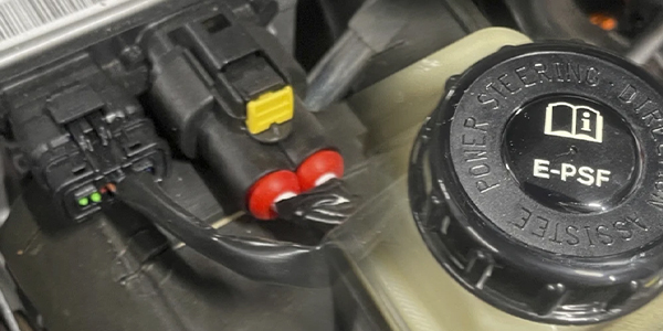
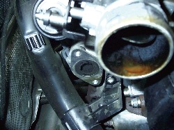
Initial reports from VW indicated a possible link to a particular brand of diesel fuel, but here in the Seattle area virtually all of the available fuel comes from one source. Most of the techs I’ve talked to seem to agree that the problem is related to the EGR cooling system (see Photo 1). Why it affects only some cars, but not all, is not quite clear at this point.
Inspection Process
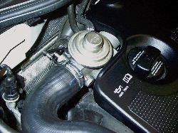
During routine maintenance, I started removing the inlet tube (see Photo 2) to the intake manifold as part of any service.
 I do this for two reasons:
- To make sure that the shut-down flap (intake manifold changeover valve) still moves freely; more on this later.
- To look into the manifold to judge the extent of plugging.
VW has indicated that a buildup of up to 10 mm is acceptable. I look at 10 mm as a warning that the engine has a problem that needs to be addressed to prevent a gradual loss of power and driveability. Since air flow through the intake system is read by a Mass Air Flow (MAF) sensor, the engine control module will tend to make fuel flow decisions based on incorrect inputs. The failure of the primary MAF (at the filter) may, in fact, be a contributing factor to the carbon problem. In most cases, when the intake plugging is severe, a MAF replacement is needed to restore full power, after cleaning the intake. The inspection is simple enough. Using a pair of pliers designed for the spring-tension clamps used by VW, remove both of the clamps that retain the hose to the distribution tube and the intake housing. Remove the hose and inspect it. There will almost always be some carbon at the EGR valve shaft, but the amount there is not of any big concern as long as the valve still operates, which can be easily tested with a vacuum pump. Doing an EGR test as you would on a running gasoline engine, where an open EGR valve will have an immediate effect on idle quality, won’t work on a diesel.
The TDI really doesn’t care where it gets air; it just needs all that it can get. If the amount of carbon buildup is not excessive, and the car runs good, you’re done. Put the intake hose back on, hook up the EGR valve vacuum hose and double-check that the shut-down flap operates freely, and test the flap with a vacuum pump attached at the actuator. Finish the rest of the service, and get the car back to the customer.
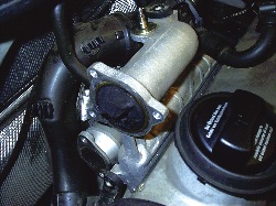
If there is evidence of carbon beyond the EGR housing (see Photo 3), you will have to make a decision to either fix it now, or let the customer know there is a problem that will continue to reduce performance and reduce fuel mileage.
Caution!
Before we go any further on this matter, let me caution you that you cannot “spray” any liquid into the intake on a diesel. Even a tiny puddle of liquid sitting on the top of a piston can cause a hydrolock condition that can bend rods, or worse yet, you could also break just enough carbon loose to lodge in a valve and cause piston-to-valve contact. These engines get real expensive, real fast when parts break. The only way to repair a carbon buildup problem is to disassemble and clean the intake components.
Cleaning
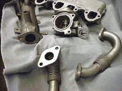
I’ve used a number of cleaning methods on the TDI intake system over the last few years. Initially, I spent several hours with a sharpened piece of metal, or a ground screwdriver and carb cleaner. We then went to media blasting to remove the carbon, sometimes with less-than-complete results. We now send out the components to a machine shop for ultrasonic cleaning (see Photo 4), and the results are fantastic. Whatever method you use to clean the intake system, make sure that as much as possible of the carbon is removed, because the problem will probably recur, and the cleaner it is at the start, the longer it will last.
VW has made life a little easier for us over the last few years by using quality hardware, especially in engine assemblies. There still is the problem of them using socket-head fasteners, but as long as the tools you use are in good condition, there should not be a problem with stripping. I’ve made it a rule that when removing socket-head fasteners from dissimilar materials (steel fasteners into aluminum), that I tighten them just slightly before removing. This almost always works, with a quick snap to loosen. To perform the intake cleaning process, the intake manifold, EGR valve, EGR cooler and all connecting pipes must be removed. This is a fairly straightforward process once the plastic engine cover is removed. The intake systems are all similar but there are slight differences between models and engine codes.
The example I’m using is the ALH engine in a 2000 Jetta. This model seems to be especially susceptible to intake deposits, again for no apparent reason. One of our customers has nearly 300K on his Jetta, and I’ve had to perform this procedure three times. The first at 40K, the second at about 120K and the third time at 220K. We’ve had many discussions about this, and neither of us has any idea why the mileage interval between services would change.
At this point, the ports at the head seem to be staying relatively clean. Possibly the cylinder head temperature is high enough to burn off the carbon at this point. Once the manifold is removed, you’ll need to make a determination whether cylinder head cleaning or removal will be needed. I’ll leave that for a future article.
Disassembly Procedures
Here is the process for removing, inspecting and cleaning the intake system. Note: The engine should be cold before you start this procedure.
- Remove the upper and lower engine covers.
- Disconnect and remove the inlet hose from the EGR valve. Remove the hose between the primary MAF and the inlet hose to the turbocharger. Then carefully disconnect the PCV hose from the intake tube, remove the mounting bolts for the tube and release the clamp at the turbo inlet to remove the tube. You’ll need to remove this tube to allow access to the fasteners for the manifold and EGR cooler. There may be a vacuum hose to the wastegate attached to the tube that will also need to be disconnected.
- Release pressure in the cooling system by removing the reservoir cap, then clamp off the two coolant hoses to the EGR cooler. Remove the hoses from the cooler. Now remove the inlet and outlet pipes to the cooler and from the exhaust manifold and EGR valve housing. Remove the EGR housing after disconnecting the vacuum lines for the EGR valve and changeover valve. A word of caution here from experience: Since the actuator for the change-over valve is plastic, it’s easier to cut the vacuum line and splice it later, than remove it and risk breaking the nipple at the actuator.
- Remove the changeover valve control valve and hoses from the manifold. You can just tie it out of the way rather than removing all of the hoses, again with the plastic!
- Remove the EGR cooler from the manifold. There are usually three tabs holding the cooler to the manifolds. Now remove the manifold; there are six socket head bolts.
- Though not mandatory, I remove the changeover actuator by removing the mounting bolts and carefully prying off the rod at the linkage. I do this just to protect the plastic actuator, which, the last time I checked, still was not available as a separate part.
Inspecting the components is fairly straightforward. If it’s plugged with carbon, it needs to be cleaned. Check the EGR valve and changeover valve for free movement and, even after cleaning, do a close examination to be sure there are no large pieces of carbon that could get loose and cause problems. The EGR cooler should be as spotless as possible, since this is probably where the carbon problems starts. Like plugged heart arteries, when the carbon starts to form, the buildup just gets worse. Make sure that the EGR valve pintle shaft moves easily with vacuum applied.
Reassemble everything you removed and use new gaskets. The gaskets are embossed, multi-layer metal, so they really are not reusable. There can be a significant amount of pressure in the intake system when the turbo is charging. Torque the manifold and the attaching parts to ensure there is no warpage from over-tightening.
Road Test
After completing the decarbon process and reassembling the intake system, it’s time for a road test. You should notice a substantial increase in power, as well as be able to actually hear the turbo spool up. Watch for any sign of excess smoke from the tailpipe, which could indicate that there’s still a problem that caused the plugging in the first place. From my experience, if the power still is not adequate, but there are no fault codes, the MAF is most likely the culprit. Other factors could be leakage in the intake system, causing a loss of boost, bad fuel or a seriously plugged air filter. Of course, there could be other problems, but unless the engine was assembled incorrectly (in which case the valves would have already hit the pistons) or the engine management system has failed, very little else ever goes wrong.
Manifold Changeover Valve
I noted above that there is a shut-down valve in the EGR valve housing. The purpose of this valve is to momentarily close the throttle when the engine is turned off, to keep it from “dieseling.” On the cars that don’t have this component, there are almost always a few more engine revolutions after the key is turned off. The problem is that if the valve sticks closed (it should pop right back open after the engine stops), the engine won’t restart. The first time this happened to me was on a TDI that would crank but not start. After checking everything else, I noticed that I would hear a little “pop” noise and then the engine would start.
Finishing Up
This problem should be taken into account before selling a customer on a TDI. But I wouldn’t say this is a deal killer. The fact is, once fuel prices return to normal (high diesel prices on the West Coast are eroding the advantage of fuel economy), the TDI would be an excellent choice for a commuter or distance traveler. They really are great “driver” cars. With an automatic transmission especially, it’s very hard to tell the performance difference between gas and diesel. The other systems on these cars are identical to their gas-powered siblings, so other repairs are right on par with other V-dubs.
Some 1998-2003 Golf, Jetta, Jetta Wagon and New Beetle models with 1.9L TDI may exhibit poor throttle response.
Note: Perform Steps 1 through 9. If any of these steps reveal a problem, repair or adjust as necessary and then road test the vehicle to determine if the customer concern has been eliminated prior to continuing with step 10.
Service Procedure
- Check the engine control module (ECM) ground connection.
- Check the injection pump timing.
- Check the snow screen (if applicable) at the intake air duct.
- Check the vacuum hoses.
- Check the EGR valve and the intake manifold air flap (integrated in EGR valve).
- Check the MAF sensor and the EGR valve, including the solenoid valve.
- Check the crankcase ventilation system.
- Check the engine oil level.
- Check fuel quality.
- Inspect the ECM ground (GND) connection for corrosion, a poor connection or no connection.
- Check the start of the injection pump timing. See Repair Manual, Group 23 – Diesel Fuel Injection, “Start of injection, dynamically checking and adjusting.”
Note: It’s advised to adjust to the upper range. - Check the snow screen (located below the left front fender in the air duct; see 3, Figure 1) and clean as necessary.
- Inspect the air cleaner element (see 1, Figure 1) for proper installation. If the air cleaner element is deformed due to improper installation, this may cause the MAF sensor to fail.
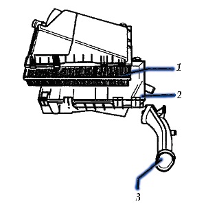
- Replace as necessary.
- Check the integrity of all vacuum hoses and connections, and repair as needed.
- Check the EGR valve and intake manifold air flap (integrated in the EGR valve).
- Remove the intake hose (see 1, Figure 2) at the EGR valve.
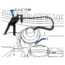
- Remove the vacuum hose from the EGR valve.
- Connect the hand vacuum pump (VAG 1390) to the EGR valve.
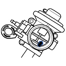
- Apply vacuum and make sure the air flap (see arrow, Figure 3) opens and closes freely. If the flap does not open and close freely, replace the EGR valve/flap.
- Check for correct function of the MAF sensor and EGR valve, including the solenoid valve (see the repair manual for procedure and operation ranges.)
- In addition, the MAF sensor must be full-load tested. See “Evaluating measuring value blocks at full load” in the repair manual, Repair Group 01 — On Board Diagnostic (OBD).
- Before replacing any parts (MAF sensor G70, EGR solenoid valve N18), ensure that the wiring is OK and the electrical connections are clean and functioning properly. If they are, replace the MAF sensor.
- If the MAF sensor (G70) failed the full-load test and, after replacement of the MAF sensor, full load value still cannot be attained, check the turbocharger (consult the repair manual).
- Inspect and ensure that the crankcase ventilation system is working to OEM specifications.
- Check and adjust the engine oil to the proper level, if necessary (do not overfill).
- If the condition occurred suddenly, there may be a fuel quality issue. If the fuel is suspected to be of poor quality, drain and refill with known-good quality fuel.
Note: Since both systems work closely together, when one system malfunctions, it will directly affect the function of the other. Therefore, it’s important to thoroughly follow the procedure.
In most cases, performing steps 1 through 9 will restore throttle response. However, in some isolated cases, if all previous items are functioning according to specifications and the vehicle still has poor throttle response, it may be necessary to physically inspect the EGR valve and intake manifold as there may be excessive carbon buildup (greater than 10 mm) in the intake manifold and/or EGR valve (in higher mileage vehicles).
Note: While some carbon buildup is normal and is not a concern, excessive carbon buildup (greater than 10 mm) is related to fuel quality and soft driving behavior (operation at low speeds, short-distance driving, and under extremely cold and damp operating conditions).
Courtesy of ALLDATA.