So Why Do We Have EGR?
By Glen Beanard, technical contributor
The Exhaust Gas Recirculation (EGR) system was created in the early 1970s for the same No. 1 ranking motivation that drives every other engine management system design — to reduce emissions. The EGR valve targets one specific pollutant, oxides of nitrogen (NOx).
Under normal combustion, the oxygen (O2) in the air plus hydrocarbons (HC) in the fuel combine into water (H2O); carbon dioxide (CO2) and the nitrogen remain unchanged. However, when things heat up in the combustion chambers to temperatures around 1,300° C or 2,500° F, all that changes. At those temperatures, oxygen and nitrogen start combining with each other and form NOx. This is a big problem because when the sunlight hits those NOx, they combine with hydrogen in the atmosphere. When that happens, we now have smog. So how do we combat that? By cooling the combustion chambers down to where normal combustion can take place.
There are several ways to lower the combustion chamber temps. Enrichening the fuel mixture, lowering the compression ratio, retarding the ignition timing, lowering the overall temperature of the engine, and reducing the amount of pure air can each lower the temperature in the cylinders. Problem is, all of those except for the last one will also reduce fuel economy. Also, each of those except for one will also raise the HC emissions. “Watering down” the intake air is the best choice. What is surprising though, is that this not only fixes a problem, it also brings efficiency improvements with it. It is a win/win situation.
OK, so how are we going to “water down” the air mass? Obviously, we aren’t using actual water, that is only a figure of speech. The air coming into the engine contains oxygen, so it supports combustion, and must have a certain amount of fuel mixed with it. If we are going to dilute that, we’ll need an inert gas to blend in with it, right? We are looking for something that doesn’t support combustion and doesn’t have to be met in the cylinder with a certain amount of fuel.
Carbon dioxide and carbon monoxide are both inert gases right? So, let’s just add a pressurized cylinder under the hood, and shoot a little of either of those gases into the intake to water down the fresh air entering the cylinders. That would work, right? Yes it would, and so would a lot of other gases, as long as they are inert. However, now we’d have a new problem. We’d now have this pressurized tank that we’d have to keep refilling. Good thing we have an endless supply of what we need coming out of the tail pipe already. All that has to happen now is to come up with some kind of way to divert some of that back into the intake manifold.
So now we have the Exhaust Gas Recirculation (EGR) system.
Theory and Operation
Gains in efficiency were mentioned earlier — how does EGR help efficiency? There are two main sources of the efficiency benefits, reduced pumping loss and the ability to advance the ignition timing.
The addition of the EGR gases slows the burn time down. Since the fuel burns slower in the combustion chamber, the ignition timing can now be pushed to where the chemical energy in the fuel can be put to better use.
What about the reduction “pumping losses”? See Figure 1. The EGR valve actually becomes a second “breathing” source for the piston. On top of that, the EGR gases actually “choke” the combustion action some. In this case, it causes the driver to have to open the throttle plate a little further than compared to a vehicle with no EGR system. When this happens, the air flows past the throttle plate with less restriction. As a result, the efforts used by the engine to “pump” the air into the cylinder are reduced. The intake stroke becomes that much less work to achieve.
If it’s a little hard to imagine that way, think of how some engines may benefit from dual exhaust systems. Depending on the engine, dual exhaust is known for increasing engine performance and efficiency. That is because dual exhaust can reduce pumping loss through a less restrictive exhaust stroke. That is no secret. EGR does the same thing on the intake stroke because the driver opens the throttle plate further, this effectively reduces the intake restriction, which lowers the pumping losses on the intake stroke.
EGR gases are hotter than fresh intake air. So how does it cool the cylinder when it actually heats the intake air charge? This isn’t about the temperature of the air charge. The cooling action doesn’t take place on the intake stroke. The cooling action takes place on the power stroke by controlling the combustion action.
Think about this for a minute: Picture a bonfire with five logs burning. The logs are stacked three on the bottom and two over the three in a pyramid formation. The logs are making contact with each other. With a fire burning in this manner, the logs are sharing heat energy with each other. The fire will have a tendency to grow at its own rate and the heat energy between the logs will be very intense. Now, imagine the same logs again, only separate them and pump a fog between them. What would happen to the fire? The second fire won’t be as intense between the logs as the first one.
Also, most importantly, the fire can now be controlled. The first fire example had no control. The fire was allowed to grow at its own rate. The second one could be controlled by varying the amounts of fog injected into it, and therefore it is not allowed to just run wild. That is the basic principle behind how the EGR gases cool the combustion chamber. The EGR gases spread the air and fuel molecules apart so that they aren’t allowed to just burn as fast and hot as they otherwise could.
Now that the burning action in the cylinders is being controlled, the ignition timing can be advanced to take better advantage of the energy being generated. This is where another efficiency gain comes into place.
Notice the tightly knit relationship between EGR flow, Timing Advance and Engine Load in Figures 2 and 3.
Though the overall purpose and operation are the same across the board, there are some details that change from vehicle to vehicle. For example, an EGR can be opened by vacuum control or an electrical signal. The EGR valve might “dump” all of its gases into the intake plenum at one port, or it may distribute a small amount into each of the individual intake runners feeding the cylinders. Likewise, the measuring and controlling of this valve varies from vehicle to vehicle. For this part of the discussion, we will be using Ford EGR systems to reference. Much of this discussion will be only applicable to Ford, yet still some may apply similarly to other makes. Be sure to always review information specific to your vehicle’s make and model before any diagnostics or repair are attempted.
Typical Ford DPFE and PFE EGR Systems
In this type of EGR system, the EGR valve is pneumatically controlled by the PCM through an EGR control solenoid called an EVR (EGR Vacuum Regulator).
 The PCM duty cycles the ground to the EVR. The EVR pulses vacuum (up to 7 inches) to the EGR in response to the “on” time duty cycle present at the EVR’s ground, see Figure 4. The resistance through the windings of the EVR should be between 26 and 40 ohms. The PCM makes electrical continuity checks of the EVR. If there is an open or short in the circuit to the EVR, the PCM will set fault codes P0403 and/or P1409.
DPFE stands for Differential Pressure Feedback EGR sensor. The “D” in DPFE is also sometimes said to stand for Delta. Delta is a Greek word meaning “change” and is also correct. The PFE was the early version of what a DPFE is today. The DPFE is newer than the PFE, however it is not the newest form of EGR flow monitoring. It is, however, currently the most common form being dealt with in repair shops due to factors such as age and volume.
 The DPFE and PFE monitor pressure drop. In order to achieve this, a restrictive orifice is added to the EGR supply tube. See Figure 5. When the EGR valve is closed, the pressures are equal on both sides of the orifice. However, when the EGR valve opens and the gases flow, a pressure drop occurs on the downstream side of the orifice. The DPFE monitors both sides of the orifice, the PFE only monitored the downstream side.
The PCM uses a voltage drop method to read the DPFE. The signal wire actually has 5 volts on it exactly the same as the 5-volt reference wire does. In the at-rest position, the DPFE drops this voltage to 1.0 volt. Some older model DPFE sensors dropped the signal voltage to as low as 0.5 volts at rest. As the DPFE senses a pressure change across the orifice, its internal resistance climbs. The signal voltage then rises, and so does the voltage displayed on the DPFE PID. At an infinite resistance on the signal wire, approximately 4.8 volts can be found.
Its older brother, the PFE, functioned in the same manner, except for the voltage-to-pressure relationship was backward from that of the DPFE. In the case of a PFE, at-rest voltage was high (usually around 3.5 to 4.0 volts). As the PFE sensor detected EGR flow, the signal voltage lowered. The DPFE electrical circuits are monitored and if an electrical problem exists there, fault codes P0405, P0406, P1400 and/or P1401 maybe set.
Every time the engine is at idle, the PCM monitors flow via the DPFE and, of course there should be none. If the DPFE voltage is high, indicating EGR flow, the PCM will set a fault code P0402. This can be caused by a sticking EGR, a sticking EVR or by erroneously reading the DPFE.
The PCM tests upstream DPFE hose for restrictions and for being torn by inspecting the exhaust pressure present on that hose once per drive cycle. If the PCM determines that there is no exhaust pressure available at the upstream hose, it will set a code P1405.
While cruising at a steady rate, and the EVR duty cycle rate is high, the PCM monitors the flow through the EGR system. If the PCM determines that the system is not flowing adequately, it will set fault code P0401 or P1408 (reserved for KOER self test only). This can be caused by a restricted EGR, broken vacuum lines to and from EVR, a mechanically faulty EVR, a sticking EGR valve, or erroneously reading the DPFE. This test is run continuously when conditions are met.
Stepper Motor EGR
The stepper motor EGR is an electrical EGR valve. It has 52 increments (steps) from fully closed to fully open that are directly controlled by the PCM. See Figure 6.
 As the EGR valve opens, the Temperature Manifold Absolute Pressure (TMAP) sensor detects the rise in manifold absolute pressure (or drop in manifold vacuum) as well as temperature of the air charge inside the manifold. The PCM “sees” the changes in manifold pressure as more or less EGR flow. In some applications, the temperature detection is used as a second IAT sensor. The TMAP sensor on this vehicle is not used for engine load calculations. This vehicle still uses a MAF sensor for load calculations. The TMAP sensor on this system is used in place of the DPFE sensor. If the PCM detects too much or too little of flow, a P0400 is set. A P1408 is the same as a P0400, but only set during KOER self test.
The PCM monitors the circuitry to the EGR valve from the EGR coil drivers. The resistance of the stepper coil circuits should be between 20 and 24 ohms. If the PCM detects a short or open circuit, it will set a code P0403. If a P0403 is set, the PCM will disable the EGR valve operations and all additional EGR monitoring.
ESM System
The EGR system module (ESM) is Ford’s latest EGR system for gasoline engines. It is an EGR valve, EVR, MAP and DPFE sensor all rolled into one package. See Figure 7.
Though the DPFE sensor on an ESM is referred to as “DPFE” by the scan tool and also wiring diagrams, it is not a traditional DPFE sensor as used on the older EGR system. It is actually two separate MAP sensors. One MAP sensor is used to measure EGR flow, after the EGR valve seat and before the flow restrictor built into the EGR base gasket. The other MAP sensor is measuring manifold pressure. The MAP sensor that is actually measuring manifold pressure, serves slightly more of a purpose than to just help figure out EGR flow. This MAP sensor is also used to calculate BARO at KOEO. This does not mean that BARO is solely calculated from this MAP sensor. The Ford PCM still uses MAF while running at 3/4 or more throttle to update BARO. However, when the engine is at KOEO, the BARO will be changed to suit the MAP sensor in the ESM.
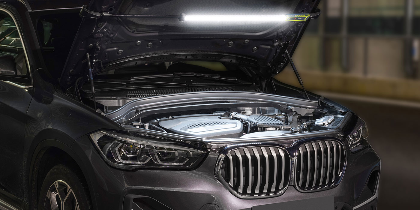
Diagnostic Tips  On this 4.6L Ford engine, the EGR is a plenum dump type EGR. See Photo 1. The fault code retrieved is for “EGR inefficient flow,” a P0401. So what do you do? Obviously, the thing to do next is inspect the DPFE voltage and to flow test the EGR ports.
All of this can be done in one handy test. Use your scan tool to bring up the DPFE PID (you can also use a volt meter on the DPFE signal lead). Next, select the EVR in your scanner’s bidirectional controls menu and open the EGR to 100% (if you are not using a scan tool, ground the EVR solenoid). Watch the DPFE volts and listen to the engine. In one step, we are testing the EVR, EGR, vacuum to and from EVR, DPFE sensor and the orifice inside the EGR supply tube. What happens will determine where to go from there.
In this case, the EGR valve did open up, and some flow was detected by the DPFE. The engine ever so slightly stumbled. See Figure 8. Notice the DPFE volts and the minor fluctuation in the engine rpm on the data capture. This points to a restricted EGR.
If no change in DPFE or engine rpms was found at all, then either the EGR is completely stopped up or the EGR valve isn’t opening due to a broken line, faulty EVR or no B+ to EVR. If the engine stalled or stumbled heavily but there was no change in DPFE, then possibly the DPFE is faulty or the orifice in the EGR supply tube is missing. The presence of the orifice can be tested by using a vacuum gauge on the upstream DPFE hose with the EGR wide open. Normally, that hose will have a measurable vacuum around 5 to 10 inHg on a free-flowing EGR and good orifice in the tube. Whether you are using a scan tool or not for this testing, don’t forget to consider the PCM’s ability to open the EVR and read the DPFE in your test results.
In Figure 9, the vehicle’s throttle body was removed, and the EGR ports were cleaned out. After that, the EGR system was retested in the same manner as before. Notice the DPFE readings of a clean EGR system and the disruption it caused in the engine’s running.
The next vehicle is a Ford Contour with a 2.5L engine. The fault code is a P0401. The DPFE sensor is stuck at 2.86V (see Figure 10),  so the above test has to be modified a little. The EGR valve is commanded 100% as with the last example. Flow testing is done by installing a vacuum hose in the upstream hose and listening to the engine. No change in engine running quality is detected and the vacuum gauge barely twitches on the zero mark. The vacuum hose is then removed from the EGR valve to listen for the valve to slam shut with an audible “slap.” The “slap” of the EGR valve is heard, proving that it did open. Of course, this points to a restricted EGR.
The throttle body is removed for cleaning and is found to be completely stopped up. See Photo 2. The passages are cleaned, see Photo 3. The system is tested after all repairs. See Figure 11.
 The 3.8L and its big brother, the 4.2L, use individual EGR ports in the lower intake to distribute the EGR to each cylinder. This poses a new issue as with another example, an E-250 van with a 4.2L engine. The complaint was Check Engine light on and engine misfire. The fault codes retrieved were P0401 and P0303 (cylinder #3 misfire). When lightly loading the engine in the bay, the engine began skipping heavily. Using the scan tool to command the EGR to close, the engine stopped misfiring with the EGR valve closed (a non-scan tool method would be to unplug either the EGR valve or EVR). Maximizing the flow in the EGR ports revealed only a peak DPFE voltage of 1.5 volts. The upper plenum was removed for cleaning.
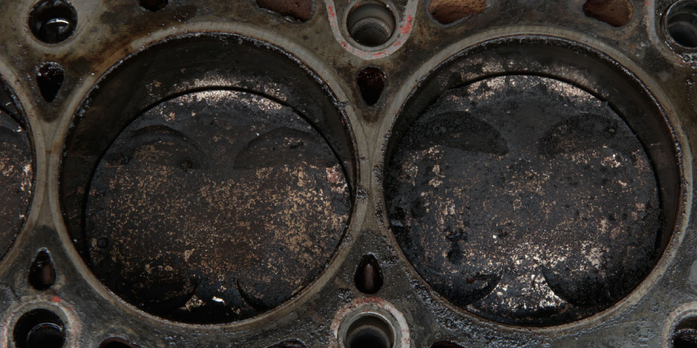
 All of the EGR ports were restricted except for #3 cylinder. See Photo 4. That caused the #3 cylinder to become overwhelmed with extra EGR gases. With that cylinder overwhelmed, it would misfire on that cylinder.
I hope that some of the information provided here gives you a better understanding of the EGR system and will prove useful to you in the future.
| Next Generation Mobile A/C Product to Meet Global Warming Regulations
Sinochem Modern Environmental Protection Chemicals (SMEPC), Houston, TX, recently announced plans to produce new, proprietary fluorochemicals for refrigerants that will meet the European Union (EU) F-Gas requirements to reduce the global warming potential (GWP) of refrigerants in future automotive air conditioning systems. The new refrigerants will have a GWP lower than 150 and will be compatible with existing automotive air-conditioning products. “Sinochem intends to establish itself as a leading supplier to the global mobile automotive air-conditioning industry through the supply of high-quality products meeting current and future industry demands” said Michael Marshall, director sales and marketing for Sinochem USA. Sinochem produces fluorochemical refrigerants in two production units in Xi’an, China. An additional fluorochemical complex with a research and development center is under construction near Shanghai, China, and will become operational in 2007. The research and development center will be dedicated to developing a comprehensive line of fluorochemical products. For more information, contact Sinochem USA. Inc., at 713-686-0700. |