Give me an unusual tire wear complaint and I’ll give you a tire wear problem that begins and ends at the steering knuckle. A typical example is an average undercar shop aligning a conventional MacPherson strut front suspension on a late-model Asian SUV. The left-front or driver’s-side camber is -0.8º, or negative eight/tenths of a degree, at the very edge of the alignment machine’s “green zone.” The right-front camber is nearly centered in the green zone. Since the camber was in the green zone, the vehicle was returned to the customer with the -0.8º left-front camber issue.
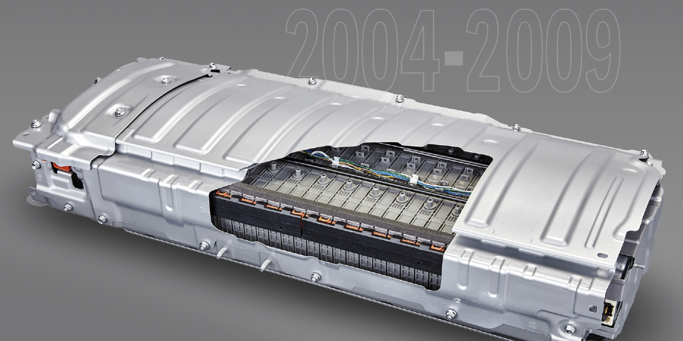
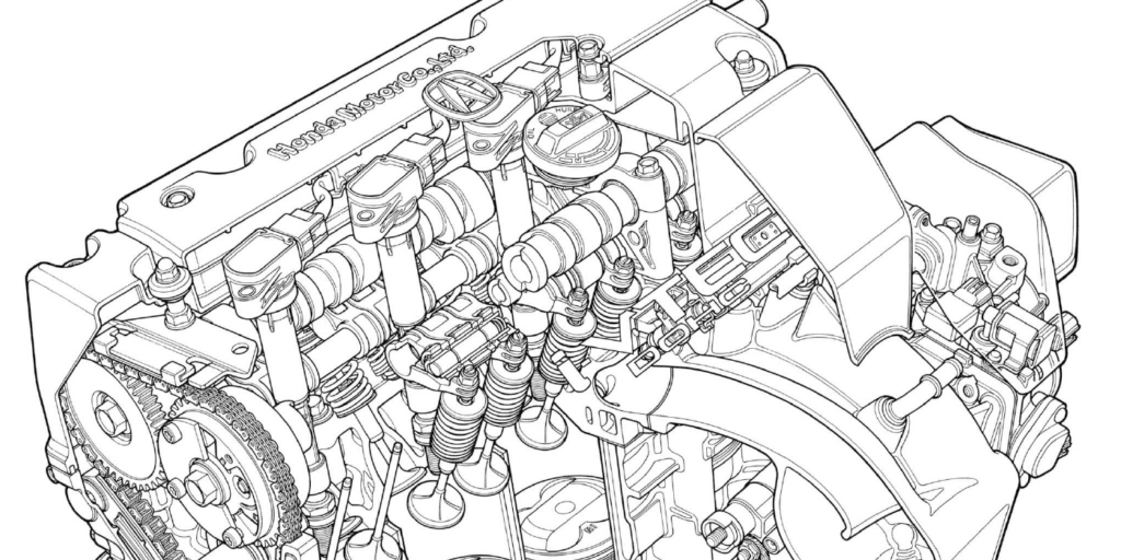
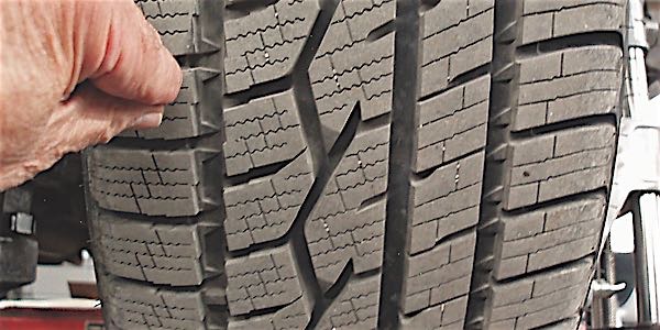
But diagnosing this green-zone camber problem requires an understanding of steering geometry far beyond what a basic knowledge of camber, caster and toe angle can solve. To make matters worse, the shop might have missed an opportunity to sell a pair of MacPherson struts and even a new steering knuckle, both of which could be diagnosed by interpreting the data displayed on a modern alignment machine. See Photo 1.
STEERING KNUCKLE FUNCTIONS
Three basic components of the vehicle’s steering geometry are built into the steering knuckle: steering axis inclination (SAI), included angle (IA) and turning angle, or turning radius. Since caster angle is built into the chassis rather than the steering knuckle, we’ll ignore caster for the moment.
STEERING AXIS INCLINATION
To create SAI, the upper strut support bearing is mounted inboard of the lower ball joint. To illustrate SAI, draw an imaginary line through the upper strut support bearing and lower ball joint to the road surface. With original equipment wheels and tire sizes in place, this imaginary line should intersect within the tire’s center tread bar. Next, draw a vertical line (0º camber) from the center of the tread bar to the top of the tire. The difference between those two angles is steering axis inclination. From true vertical (0º) to a line drawn through the center of the tire tread from bottom to top is camber angle. SAI is useful for diagnosing bent control arms and spindles and damaged strut towers and subframes. Since SAI is more active during a turn, steering and tire wear problems will occur more frequently during city driving conditions.
CAMBER ANGLE
To establish a near-zero camber angle, the wheel bearing spindle is mounted at a near-horizontal angle to the inward-leaning MacPherson strut. Most import vehicles specify a slightly negative camber angle, which means that the tire leans in at the top to increase the tire’s tread contact area during cornering. But, since the -0.8º left-front camber reading on our Asian SUV is at the very edge of the green zone, a bent spindle or strut might be indicated.
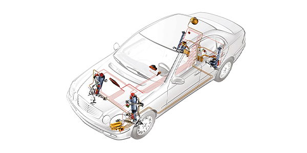
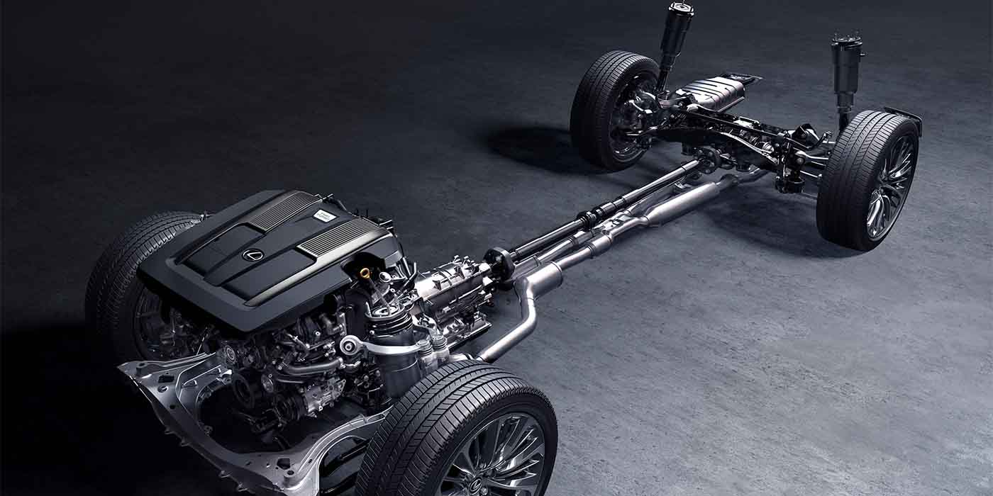
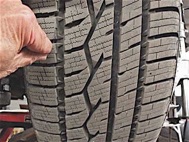
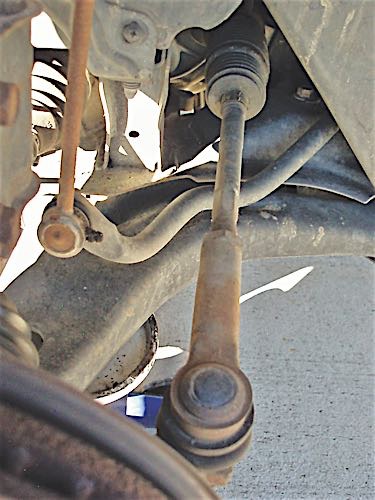
If we follow the manufacturer’s recommendation of allowing a side-to-side camber variation of no more than 0.050º, we must repair the excessive negative left-front camber angle by replacing the steering knuckle or strut or by straightening the strut tower. See Photo 2.
CAMBER NOTES
Camber angle is one of two tire-wearing angles (the other being toe angle) and is very sensitive to crowned road surfaces. Let’s assume that the green-zone range of camber specifications are -0.80 to +1.00 degrees. If the left-front camber is -0.80º and the right-front is +1.00º, both are at the outer limits of the green zone. But this cross-camber difference will tend to pull the steering to the right on a flat road surface. This tendency will be exaggerated by road crown. Road crown will also increase the tendency of the left-front tire to wear on the inside tread bar and the right-front tire to wear on the outside tread bar. If the left-front and right-front camber readings were switched side to side, (+1.00 left/-0.80 right), the vehicle would steer much better on a crowned road and tread bar wear would be reduced because both tires would now be running closer to a zero camber position.
INCLUDED ANGLE
The IA is the sum of SAI + camber angle. When IA is added to the alignment equation, we can more accurately diagnose the type and the extent of suspension system damage. For example, if the “cross-IA” difference equals or exceeds 1.5º, we’re narrowing our search to a bent spindle, knuckle or lower ball joint stud. We’ll have more on that later.
TURNING ANGLE
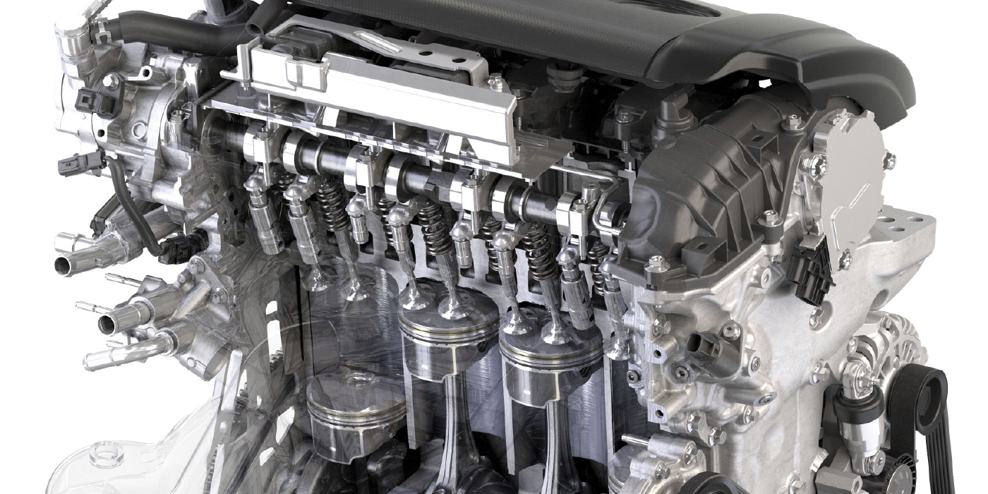
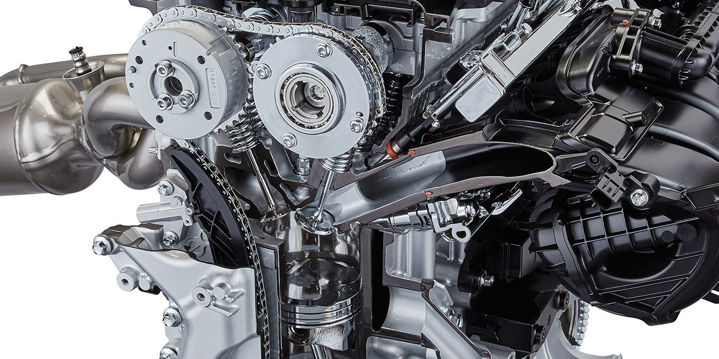
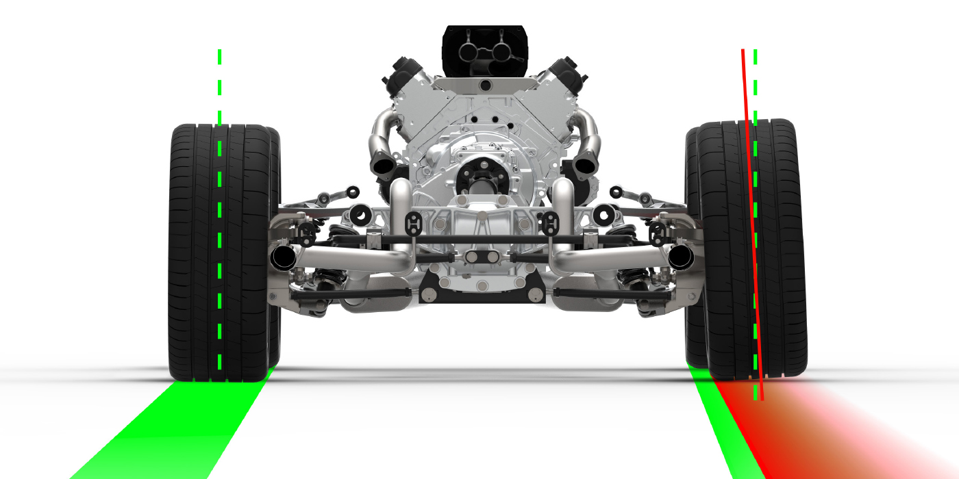
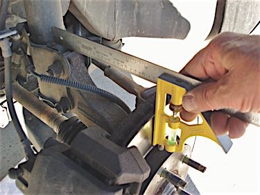
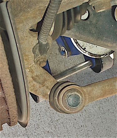
Since the inside wheel turns on a shorter radius than the outside, the turning angle increases toe-out to produce approximately a 20º turning radius at the inside wheel and an 18º radius at the outside wheel at full-lock. If the steering arm built into the steering knuckle is bent or a lower control arm is dislocated, the change in toe-out will result in the tire scrubbing during a turn. See Photos 3 & 4.
STEERING CENTERING
As the front wheels are turned from lock to lock, we’ll notice that the car rises slightly in each direction because each spindle travels in a rainbow-shaped, arched path. Due to this aspect of steering geometry, SAI returns the front wheels to “high point” as the steering wheel is released. Remember that SAI is always measured with the front brakes locked to prevent tire rotation and with straight-ahead toe angle adjusted close to specification. The chassis might also be lifted slightly to reduce weight on the suspension, which allows the front wheels to swing through their full radius during an SAI measurement. Offset or extra-wide wheels make this process more difficult.
SAI/CAMBER ROLL
When combined with caster angle, SAI decreases the camber angle on the outside wheel and increases camber on the inside wheel. This effect, known as “camber roll,” improves steering by providing better tread contact with the road during a sharp turn. Last, SAI by itself won’t cause a steering pull and, in most cases, steering pull is caused by unequal cross-camber and cross-caster angles. In any case, it’s far better to turn a green-zone alignment problem into a profitable repair by thoroughly analyzing the data than for your customer to leave with his vehicle still suffering from a tire wear or steering quality complaint.
INTERPRETING SAI, IA AND CAMBER ANGLES
Since the interaction of SAI, IA and camber angles is complicated, they’re also difficult to visualize. To simplify collision damage diagnostics, most alignment equipment manufacturers provide diagnostic charts that will help the alignment technician interpret the relationship between the SAI, IA and camber angles. In any case, let’s look at four typical combinations of SAI, IA and camber angles that indicate problems with a MacPherson strut suspension:
| Condition | Probable cause |
| Camber high, SAI low, IA correct | Bent lower control arm or frame |
| Camber high, SAI correct, IA high | Bent strut, ball joint or knuckle |
| Camber low, SAI correct, IA low | Bent strut, ball joint or knuckle |
| Camber low, SAI high, IA correct | Top of strut tower bent inward |
The “camber low” symptoms might indicate that our Asian SUV mentioned at the onset with the -0.8º left-front camber reading might have a strut tower bent inward at the top or a bent strut, knuckle or ball joint. Since the above examples are meant to only be guidelines, suspected damaged can be confirmed by following these steps: To detect a bent strut shaft, loosen the shaft mounting nuts and rotate the shaft. If the camber varies while the strut shaft is being rotated, the shaft is bent. Next, place the flat part of a carpenter’s tri-square against the brake rotor and then extend the scale until it touches the base of the strut (see Photo 2). Compare that measurement with the opposite side. If there’s a significant difference, the side with the lesser measurement likely has a bent strut or steering knuckle. If the strut tower is damaged or the subframe is bent, a frame bench must be used to straighten the chassis to precise factory specifications.