For many years, most of us believed that the mass airflow system provided the most accurate measurement of an engine’s intake airflow. For one thing, not too many things can go wrong with a system that produces a single voltage or frequency input that indicates to the ECM an exact value of intake airflow in grams per second. In contrast, a typical 1980s speed density system estimated intake airflow by using inputs from the intake manifold absolute pressure/barometric (MAP/Baro), throttle position (TP), engine coolant temperature (ECT), intake air (IAT) and engine speed (RPM) sensors.
Since a speed density system has so many parts that can fail or drift out of calibration, imagine my surprise when I recently read that some of Ford’s new world-class EcoBoost engines are now equipped with speed density engine management systems!
NEW ENGINE TECHNOLOGY
Modern engine technology is changing our concept of how we increase engine torque and fuel economy. Ford Motor Company has, for example, reduced rotating friction in its world-class EcoBoost series by reducing cylinder displacement and by using roller-type bearings to support its dual overhead camshafts. Ford also has reduced rotating mass by eliminating balance shafts and their related rotating parts.
Other engine designs reduced rotating mass by incorporating a flat-plane 180º crankshaft that doesn’t require heavy counter-balance weights. To reduce engine warm-up times, water-cooled engine exhaust manifolds are now cast integral to the cylinder head, with responsive turbochargers mounted directly to each manifold. Modern engines like the EcoBoost also use variable exhaust valve timing to eliminate conventional exhaust gas recirculation (EGR) systems.
When these new technologies are coupled with current technology like wide-band air/fuel ratio sensors, electronic throttle controls with double-redundancy throttle position sensors, variable intake valve timing, direct fuel injection, pulse-modulated fuel pumps and much faster computing capabilities, we’re looking at some major advances in producing high engine torque, increasing fuel economy and reducing exhaust gas emissions.
MAF SENSOR ISSUES
To better understand the evolution of the modern speed density system, let’s take a brief look at the conventional hot-wire mass airflow (MAF) sensor.
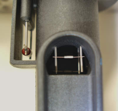
At its most basic level, the conventional hot-wire MAF sensor relies on the cooling effect that fast-moving air has on a “hot wire” resistor suspended in the air stream (see Photo 1). In short, the faster the air mass flowing past the hot wire, the cooler the wire becomes. The cooler the wire, the greater the amperage flow through the hot wire. The MAF then translates this amperage value into a direct voltage or a frequency (Hz) value indicating grams-per-second airflow to the ECM. To aid in this computation, an intake air temperature (IAT) sensor is integrated into the MAF sensor.
In other MAF configurations, a Baro sensor is added to report key-on, engine-off baro, while in conventional MAF configurations the barometric pressure value is calculated as the engine accelerates. The downside of the MAF sensor is a vulnerability to air-borne dirt and fibers caused by improperly installed air filters.
Since any type of airborne debris produces either an insulating or a radiating effect on the hot wire, a positive or negative air/fuel calibration error occurs as dirt accumulates on the MAF’s hot-wire resistor. The most common indications of a dirty MAF sensor are an incorrectly calculated barometric pressure, an incorrectly calculated engine load and abnormal fuel trim values.