The American writer Irene Peter said it best: “Just because everything is different doesn’t mean anything has changed.” By 2018, I thought everything had changed since the days of On-Board Diagnostics I (OBD I). Since OBD I evolved into OBD II in 1996, many things did indeed appear to be different. But, once in a great while, engineers design a vehicle that is slightly ahead of its time. For me, it was a 1995 Nissan pickup (see Photo 1) equipped with the 3.0-liter V6 engine and manual transmission. Surely being an oddity, it would start and run with the distributor disconnected. (Huh?)
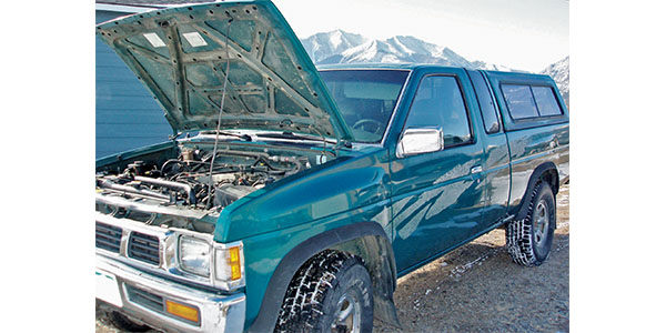
The “Just because everything is different” part began with a local shop calling about an intermittent loss of power complaint on the Nissan. Considering the hundreds of these ultra-reliable pickups I’ve worked on during the past two decades, I was amazed that, in 2017, I had actually discovered a new Nissan diagnostic problem. The “doesn’t mean anything has changed” part is that, somewhere, there’s a veteran Nissan technician who knows the Diagnostic Solution to this problem. But, let me give you my take on it.
RE-WRITING THE BOOK
Looking back, the modern electronic era began in the late 1960s when Volkswagen introduced its first electronic fuel injection system. Factory service information in those days consisted of paper manuals and live, hands-on training center classes. In contrast to factory training, the independent market depended largely upon some rather sketchy aftermarket service manuals and the unforgiving School of Hard Knocks for its education.
During the fall of 2000, the National Automotive Service Task Force (NASTF) formed and began negotiating with vehicle manufacturers to provide access to original equipment manufacturer (OEM) tooling and service information. Going a step further, the Environmental Protection Agency (EPA) began standardizing the diagnostic trouble code (DTC) identification system and the diagnostic protocols used in modern on-board diagnostic systems. For the 1996 model year, the EPA introduced the standardized, 16-pin diagnostic connector in use today. While not perfect, we’re light years ahead of where we were in 1995.
OPEN-LOOP MYSTERIES
We discovered that the Nissan would start by cranking the engine for about 30 seconds until the tachometer snapped up to a loping, 800-rpm idle speed. If we disconnected the throttle sensor, the engine would start immediately and idle normally. The difference might have been the throttle position (TP) sensor containing a throttle switch that commands the ECM to run in an open-loop, non-computed mode at closed throttle. As the throttle opens, the ECM goes into the closed-loop computed mode. Not really understanding what I was looking at, I moved on to something I could actually measure.
CODE INTERPRETATION
After moving the Nissan to my shop for a more detailed diagnosis, I retrieved diagnostic trouble code (DTC) 34 (knock sensor out of range) and DTC 55 (ECM OK). Today, researching and understanding code enable criteria is an extremely important part of the diagnostic process. Knowing how and when a code is stored in the ECM’s diagnostic memory provides valuable clues in solving any diagnostic problem.
But enable criteria and freeze-frame data wasn’t as available in 1995, so the Nissan’s DTC 34 wasn’t particularly informative. To the contrary, the DTC 55 indicated that the engine management system was working perfectly. So, I’m calling this situation a no-code diagnosis.
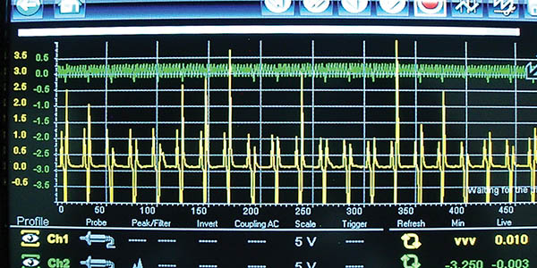
During initial testing, I noticed that the base timing was jumping plus or minus 10º on either side of the timing pointer. By extension, the erratic timing might have caused the knock sensor to produce an erratic voltage signal, which I confirmed by scoping the knock sensor’s ECM connector pin. Without enable criteria, I’m guessing that the timing variation might be causing the DTC 34 knock sensor code.
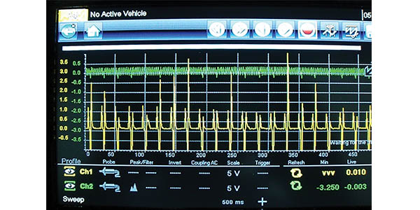
OPTICAL DISTRIBUTORS
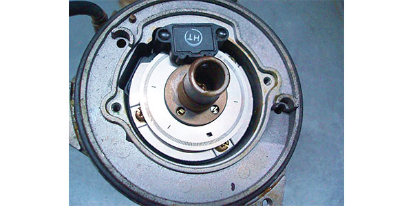
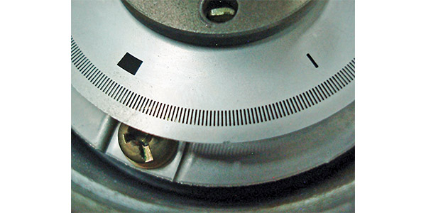
To time the fuel injectors and ignition, the Nissan’s optical distributor shines a light-emitting diode (see Photo 2) through a timing plate consisting of 360 slots identifying crankshaft position and six slots identifying camshaft position (see Photo 3). I’ve never had problems with optical distributors, other than oil and dirt contaminating the timing plate. Each time I tested the distributor, the crank/cam waveforms were in perfect synchronization. But I didn’t realize that was a temporary condition (see Photo 4).
SCAN TOOL DATA
The old scan tool I used on the Nissan requires a vehicle-specific cartridge and connector. The datastream amounts to something like eight lines. Using today’s scan tools, we can access ECM calibrations and vehicle identification number, examine data streams, run bi-directional tests, poll all modules for communications issues and codes, and store all of the above in the scan tool’s memory.
Although many aftermarket scan tools contain case studies, TSBs and code-related diagnostic service information, many technicians still use their enhanced scan tools solely as code readers, which utilizes far less than 10% of the tool’s total diagnostic capacity. This, of course, begs the question of what to do when faced with a no-code driveability complaint.

NO-CODE DIAGNOSTICS
No-code diagnostics requires a functional understanding of how the engine management system works. Our Nissan ignition, for example, is a single-coil, distributor-type system. Key-on current is supplied to the ignition module and coil positive circuit. During cranking, the optical distributor sends a crankshaft camshaft position and #1-cylinder TDC/compression signal to the ECM. This ignition timing strategy is still in use today.
The integrity of the optical distributor was confirmed on several different occasions by comparing the Nissan’s optical signal with known-good waveforms from the International Technician’s Network (iATN). This was an impossible task before the invention of the Internet. So, armed with this knowledge, I wondered if some type of electrical interference was causing the ECM to trigger the power transistor in the ignition module (see Photo 5).
For this reason, I removed some dysfunctional aftermarket electronics before I went any further. I might mention that the ECM was also activating the fuel pump and triggering the fuel injectors, as if the engine were actually running. In fact, I could quickly hydro-lock the cylinders by merely opening the throttle on the dead engine.
THE DIAGNOSTIC DETECTIVE
You’ll find the Diagnostic Solution to this month’s case study in the attached sidebar. It was, for me, a completely unexpected and unfamiliar problem. A “Silver Bullet Solution” would have been welcome, but remained hidden somewhere in some obscure bit of service information. To find the Diagnostic Solution, I needed to become a Diagnostic Detective to do the legwork needed to solve this perplexing problem. I walked many miles before I discovered that tomorrow had actually happened yesterday.
SIDEBAR
When Yesterday Is Tomorrow
To once again quote Irene Peter, “Just because everything is different doesn’t mean anything has changed.” While engine configurations change, the work involved with becoming a Diagnostic Detective has not. So, let’s take a gumshoe-tour to find our Diagnostic Solution.
1. Pin testing was difficult because the ignition coil, fuel injectors and fuel pump were simultaneously activated, key-on, engine off.
2. I accidentally diagnosed the problem by disconnecting the distributor to test the ECM circuit for electrical interference.
3. A few days later, I started the Nissan, only to discover that it was running with the distributor disconnected. I had to really think about that for a while.
4. When I originally scope-tested the distributor, the engine was running perfectly, so I assumed that all was well with the distributor’s optical sensors.
5. What I didn’t realize that the distributor sensor circuits were intermittently failing, which placed the Nissan’s ignition in a default or “limp-in” mode.
6. Under a default strategy, the ECM was using a roulette-type strategy to adjust spark timing while the engine was being cranked. The actual spark timing was very erratic, which confirmed my theory.
7. Default strategies were evidently being used by Nissan in 1995 to compensate for a failed distributor (just another sensor), which is something I would never have suspected.
8. A new distributor fixed the problem.