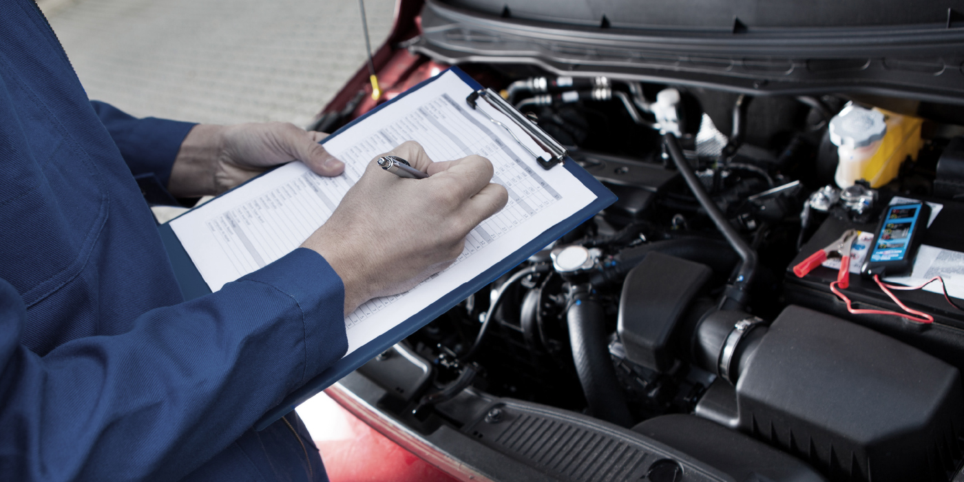

Fuel trims are a difficult topic to cover in a matter of a few pages. But this summer, an old friend and former teaching partner arrived at our local car show with the check engine light illuminated on his 2004 Holden Monaro, which was imported from Australia and rebadged and sold in the U.S. (See Photo 1). Its unique corporate history aside, this relatively rare imported muscle car had the all-too-common P0171 and P0174 trouble codes stored in its diagnostic memory. While we didn’t have time to verify my diagnosis with a repair after the car show, the car’s fuel trim data did illustrate how this type of information can be used to quickly narrow down the causes of the P0171 and P0174 codes in many other import vehicles.
LAMBDA IN A NUTSHELL
To begin, a methodical fuel trim analysis will narrow a P0171/P0174 code issue down to three basic failure categories: a mechanical malfunction (e.g., a vacuum leak or leaking fuel pressure regulator), a fuel delivery problem (e.g., a worn fuel pump or bad pressure regulator), or an air/fuel calculation error (e.g., a dirty mass air flow sensor). Since fuel trims are software-based, their operating strategies will vary among manufacturers. All fuel trim strategies do, however, share the mission of compensating for excessively rich or lean air/fuel ratios (AFRs).
A chemically correct, or “perfect,” AFR is expressed as Lambda 1.0 or as a stoichiometric AFR. Following combustion,a Lambda 1.0 mixture will theoretically exit the combustion chamber as pure water and carbon dioxide. To further the example, Lambda 1.10 indicates 10% excess air, while Lambda 0.90 indicates 10% insufficient air entering the cylinder. The Engine Control Module (ECM) corrects for either condition by increasing or decreasing fuel injector “on-time” or “pulse width.”
Enhanced scan tools display fuel trims as short-term fuel trim (STFT) or long-term fuel trim (LTFT) percentages as soon as the engine is started and the upstream oxygen sensors or air/fuel ratio (AFR) sensors begin generating signals. The PCM then assumes “fuel control” by entering what is called the closed-loop operating mode. Simply put, fuel control allows the ECM to increase or decrease fuel injector pulse width to achieve Lambda 1.0. The resulting fuel trim number indicates the percentage of fuel that’s being added or subtracted from normal to maintain Lambda 1.0.
STFT percentages indicate running changes in AFR because they are derived directly from the upstream air/fuel ratio feedback to the ECM. LTFT percentages consist of STFT corrections stored in the PCM’s “load-cell” memory. LTFT is the learned fuel injector pulse width needed to maintain Lambda under specific operating conditions. Because LTFT is a learned value, it automatically compensates for long-term fuel control problems. Due to its compensating ability, LTFT will drive the STFT to nearly zero in most cases.
The downstream rear oxygen sensor can also contribute to total fuel trim percentage, but its operating strategy is very vehicle-specific, and, therefore, beyond the scope of this column. A zirconia oxygen sensor is generally used in the downstream position. After the catalyst reaches operating temperature, the downstream oxygen sensor voltage usually hovers around 700 millivolts (0.7 volts). The total fuel trim consists of adding the STFT, LTFT and rear trim (if available) percentage numbers. For example, +5% STFT added to +5% LTFT = +10% total fuel trim. Adding +6% rear trim = +16% total fuel trim.
FREEZE-FRAME BASICS
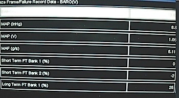
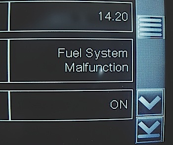
The freeze-frame data from my friend’s Monaro/GTO indicated that codes P0171 (lean) and P0174 (lean) were set at idle with the brake on and the vehicle in neutral/park. Engine runtime was two minutes, 29 seconds, and barometric data indicated an altitude of slightly less than 8,000 feet. Most important, the LTFT B1 and B2 was +25 percent. The P0171 and P0174 codes are stored when enable criteria are met and fuel trim percentages exceed approximately +25%. See Photo 2.
The failure record (FR) on B1 indicated a first failure at 624 miles previous and a last failure at 195 miles previous. The FR on B2 indicated first and last failures occurred at 624 miles, which indicates a possible bias toward B1 fuel control.
ROAD TEST BASICS
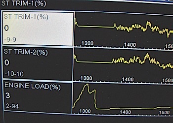
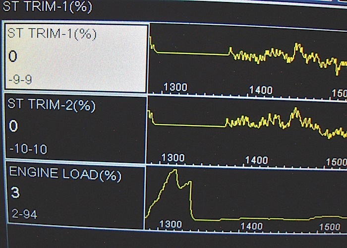
Although an extended idle didn’t duplicate the failure, road testing indicated that B1 STFT varied slightly higher than normal — between -9% and +9% — while B2 STFT varied from -10% to +10%. Accelerating at wide-open throttle, fuel trims dropped to zero as the engine showed 94% load. See Photo 3.
Since I scanned the ECM just before the car left for home, I didn’t have time to verify the actual cause. But I could recommend a diagnostic direction based solely on fuel trims: 1) The freeze-frame data was stored after two minutes and 29 seconds runtime at idle speed; 2) the freeze-frame B1 and B2 STFTs were well within the allowable 5% range; 3) the freeze-frame B1/B2 LTFTs reached +25%; and 4) the first B1 failure occurred at 624 miles and the last at 195 miles. B2 failed only at 624 miles.
The range of STFT percentages recorded during our road test was high at -9% to +10% (since -5% to +5% is considered normal). A prime suspect, the mass air flow (MAF) sensor, was showing about 5 grams per second (gps) at idle speed on a 5.7L engine. Approximately one gps per liter indicates that the MAF is measuring intake air closely enough to maintain fuel control at idle speed. At WOT, the engine load increases to 94% at peak engine speed, which indicates that the MAF sensor is accurately measuring intake air. The fuel trim percentages reach zero at WOT because the engine is operating as programmed in open loop. A richer air/fuel ratio in the 13:1 range is usually programmed for WOT operating conditions.
DIAGNOSTIC CONCLUSIONS
Since I couldn’t duplicate the problem, and because the freeze-frame data indicated that the codes were set at idle conditions two-and-a-half minutes after start-up, I’m speculating that we might have had a cracked vacuum hose that was sensitive to engine torque. At the extreme, the cause could be something like an intermittently leaking vacuum brake booster or even a temperature-sensitive intake manifold gasket. The prospect of a fuel pump/fuel delivery problem is largely eliminated since the engine maintained fuel trim under load at highway speeds. Since the last failure record was on B1, I’d begin by looking for a PCV grommet failure, a leaking vacuum brake booster or booster hose, or a similar intermittent low-speed vacuum leak that could likely be identified by visual inspection.
Modern Scan Tool Terminology
While their basic fuel trim strategy remains the same, conventional zirconia oxygen sensors have been largely replaced on the upstream side by wide-band air/fuel ratio (AFR) sensors. The zirconia sensor can sense only when the AFR is slightly leaner or richer than Lambda. In contrast, wide-band AFR sensors can sense air/fuel ratios ranging from very rich to very lean, which is why they’re used on GDI engines and other motors capable of “lean-burn” operating modes.
If you haven’t been paying attention to recent scan tool data, prepare to be confused by modern fuel control terminology. Remember that Lambda 1.0 indicates a perfect air/fuel ratio regardless of the type of fuel used. The air/fuel ratios for Lambda 1.0 are 14.65:1 for “pure” gasoline, 13.85:1 for E10 ethanol gasoline and 9.68:1 for E85 ethanol gasoline. With that said, Lambda 1.0 is required to allow catalytic converters to oxidize and reduce pollutants in the most efficient manner possible.
In contrast to the 0.2- to 0.8-volt switching signal of zirconia sensors, AFR sensors generate a very small, but steady, amperage signal. Some aftermarket scan tools will display AFR amperage, but the AFR amperage signal might also be “generically” displayed as a 0.0- to 1.0-volt signal. On the other hand, Toyota displays its AFR signal as a voltage range in which 3.3 volts indicates Lambda 1.0 or a “perfect” 14.7:1 air/fuel ratio for non-ethanol gasoline. Less than 3.3 volts indicates low oxygen content, while more than 3.3 volts indicates a high oxygen content.
Since the AFR sensor signal is most accurately measured with an enhanced scan tool, it’s also best to let the ECM/PCM store a DTC if the quality of the AFR sensor signal doesn’t meet manufacturer’s standards. If you see a data line labeled “equivalence ratio,” or “EQ,” remember that since the 2000 model year, EQ is actually shorthand for Lambda. In reality, there’s much to be learned about fuel trims. I’ve highlighted the most common fuel trim issues in this column, but remember that some fuel trim classes can last up to eight hours with very good reason.