When diagnosing a charging system on any modern import, think “smart.” I learned this lesson several decades ago when repairing a cranking, no-start condition on a 1989 Honda Civic, which was equipped with one of the first “smart” charging systems. After verifying fuse continuity, I discovered that excessively high charging voltage had destroyed the Honda’s Engine Control Module (ECM).
With a used ECM installed (ECMs were plug-and-play in those days), the engine started, which meant that the ignition module and coil had survived the over-voltage condition. Needless to say, the radio was ruined and the exterior light bulbs were burned out. I started the engine after installing a new alternator and light bulbs, only to discover a no-charging condition.
Frustrated, I researched Honda’s then-new Electric Load Detection (ELD) charging system. I discovered that the ELD had to sense an electrical load before it would activate the alternator, which is a basic “smart” charging strategy. Now that the exterior lighting had been replaced, I turned on the headlamps and, miraculously, the alternator began charging a normal 14.2 volts. In this case, the key to solving the problem was understanding electrical load in the form of amperage flowing to and from the battery. See Photo 1.
VOLTAGE-BASED CHARGING SYSTEMS
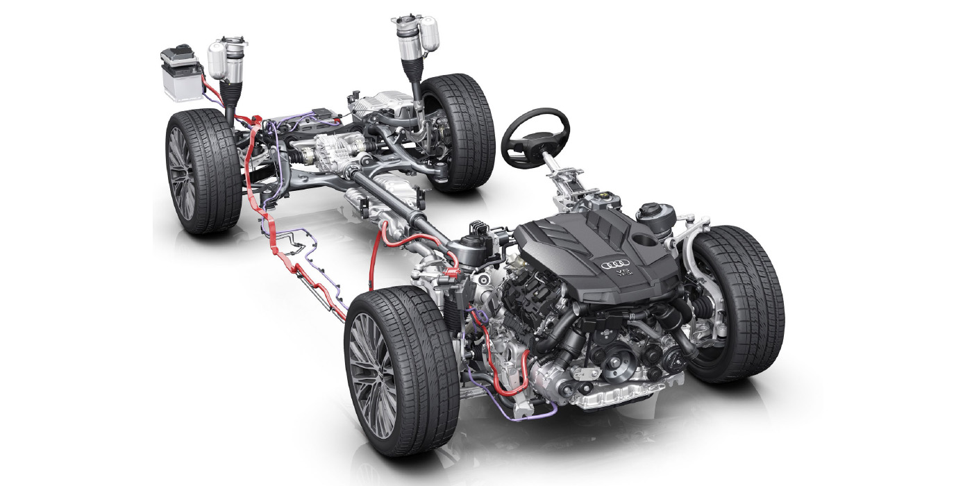
Let’s keep our “smart” charging concept simple by breaking charging systems into voltage- and amperage-based designs. To begin, we have two basic configurations of alternator field control: 1) An alternator field circuit that is completely controlled by the Powertrain Control Module (PCM); 2) the alternator field circuit that is controlled by an internally mounted voltage regulator that receives commands from the PCM to modify the alternator’s normal charging rate.
In retrospect, voltage-based systems aren’t very “smart” because their charging strategy is based only upon voltage or battery state-of-charge (SOC) and ambient temperature. Even in the days of mechanical voltage regulators, ambient temperatures controlled charging voltage via bi-metallic strips built into the voltage regulator itself.
To illustrate, 14.2 charging volts are required to overcome chemical resistance in a battery at a core temperature of 70° F. When core chemical activity is inhibited by sub-freezing temperatures, 15.0 or more charging volts are required to maintain battery capacity.
During hot summers, charging voltages as low as 13.5 volts are required to prevent boiling the water from the battery’s electrolyte when core chemical activity is at its peak. While conventional charging systems manage battery voltage very well, the alternator (or generator) operates continuously, which reduces fuel economy and increases exhaust emissions.
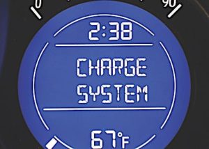
When the red “BAT” warning light on the instrument panel illuminates for no apparent reason on amp-based charging systems, think “smart.”
For example:
1. Before beginning any charging system diagnosis, test all fuses in the underhood and interior fuse boxes for electrical continuity.
2. Test battery state-of-charge (SOC) and state-of-health (SOH). A defective battery cell will create a low-voltage condition that will never be met by normal charging system parameters.
3. When diagnosing any amp-based system, remember that the amp-based system’s operation is based upon an inductive amp probe that’s connected to either the positive or negative battery cables or is built into the vehicle’s fuse box.
4. Connecting a high-amperage accessory directly to the battery positive terminal or connecting an auxiliary ground to the battery negative terminal won’t affect a voltage-based charging system.
5. On the other hand, connecting accessories to the battery positive or an auxiliary ground to battery negative on an amp-based system can cause a low battery state-of-charge because the system no longer senses total amperage flow from the battery.
6. The basic operating parameters of the amp-based system might not be met when a non-specification battery is installed in place of the original equipment battery.
7. The basic operating parameters of the amp-based system might not be met if the diameter of a replacement alternator pulley doesn’t match original equipment specifications.
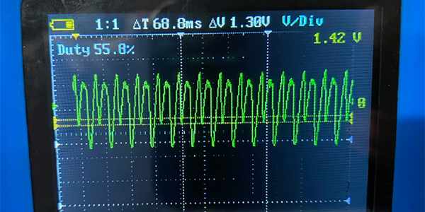
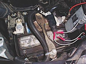
8. Most amp-based systems monitor amperage through an inductive sensor mounted on the battery cables or in the fuse box. That sensor usually generates a voltage signal to the PCM (see Photo 2).

9. Through this signal, the PCM determines the required amperage output required to carry the vehicle’s electrical load.
10. Remember that modern CAN-bus vehicles with amp-based charging systems often include a “load-shedding” feature that begins shutting down non-essential accessories when the battery’s discharge rate exceeds the alternator’s charging rate.
AMP-BASED CHARGING SYSTEMS
Amp-based charging systems are, in a word, “smart” because they not only monitor battery voltage, but also monitor amperage flowing to and from the battery through the fuse box or the positive or negative battery cables. To better explain the amp-based concept, a fully charged, flooded-cell, lead-acid battery with no electrical load should maintain 12.6 open circuit volts at its terminals. In fact, many amp-based charging systems are comfortable with a battery charged to 80% of its capacity, which is slightly over 12.4 volts.
Looking at our 1989 Honda Civic, the Honda’s ELD hadn’t activated the alternator field circuit because it was perfectly happy with 12.6 battery volts at idle speed. But, after turning on the exterior lights, the ELD activated the alternator field circuit to prevent the added load from draining the battery.
MODERN LOAD DETECTION
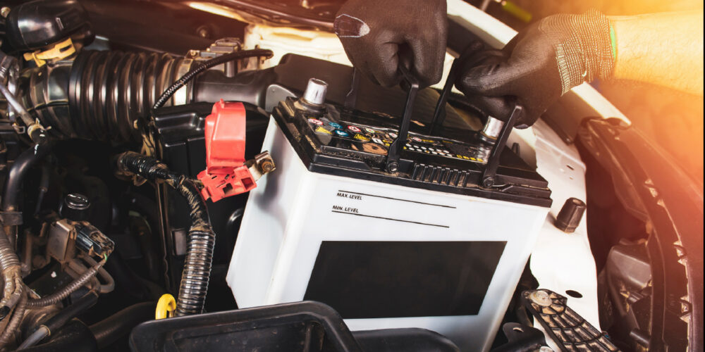
Modern amp-based charging systems are much “smarter” than the old Honda ELD system because the PCM can not only sense battery SOC, but battery SOH, engine load and driving conditions as well. BMW and other nameplates might, for example, include algorithms in their PCMs that compensate for the gradual electrical degradation taking place in all batteries. When a battery is replaced in these systems, the new battery must be “registered” to allow the PCM to reset the learned values relating to battery SOH. See Photo 3.
AMP-BASED DIAGNOSTICS
Suffice it to say that attempting to diagnose a “smart” amp-based charging system with a voltmeter is a waste of time. We might say that an amp-based charging system’s major function is to carry the vehicle’s electrical load, and its minor function is to maintain battery charge. Under the amp-based theory, the amp-based system might begin re-charging the battery by increasing charging voltage to, let’s say, 14.2 volts after the engine is started.
But, if the battery maintains its specified voltage range and no further amperage flow is detected from the battery, the amp-based system might operate in a low-voltage battery maintenance mode until it senses another electrical load. In short, the diagnostics of an amp-based charging system depend very much upon the PCM seeing voltage potentials and amperage flows at the battery that correspond to current operating conditions. If volts and amps don’t meet specified parameters, the PCM will turn on the red “BAT” warning light, regardless of what the battery voltage might be.
As the battery ages, the PCM might also increase average charging voltage to compensate for battery plate sulfation and degradation. In some cases, the charging voltage might range as high as 15.0 volts to de-sulfate a battery that’s seen a lot of short-trip driving. While these charging strategies and values are hypothetical on my part, they do illustrate the futility of diagnosing an amp-based charging system with a voltmeter.
SCAN TOOL DIAGNOSTICS
Since an amp-based charging system is normally controlled by the PCM, it’s reasonable to expect that most smart charging systems will generate a failure code. My first step in diagnosing any “smart” system is to verify indicated battery voltage at the PCM by directly measuring voltage at the battery terminals. If the indicated voltage is too high, it’s likely that the PCM is defective. In one case that I diagnosed several years ago, the PCM wouldn’t activate the alternator even though battery voltage was in the 11-volt range. Looking at scan tool data, the indicated voltage exceeded 17.0 volts. Since the PCM was “seeing” 17.0 volts, which is the threshold value for damaging on-board electronics, the PCM disabled the alternator.
If the indicated voltage is too low, high resistance might be present in the wiring circuit or the PCM might be defective. In this case, measure battery positive or B+ voltage into the PCM connector. If the scan tool’s indicated voltage is lower than the voltage measured at the PCM B+ terminal(s), the PCM is a prime suspect. In any case, before replacing the battery or alternator, learn to think “smart” when diagnosing amp-based charging systems.